Simple harmonic motion, like any motion, can be described in terms of displacement, velocity, and acceleration, and the model in Figure 10.8 is helpful in explaining these characteristics. The model consists of a small ball attached to the top of a rotating turntable. The ball is moving in uniform circular motion (see Section 5.1) on a path known as the reference circle. As the ball moves, its shadow falls on a strip of film, which is moving upward at a steady rate and records where the shadow is. A comparison of the film with the paper in Figure 10.6 reveals the same kind of patterns, suggesting that the shadow of the ball is a good model for simple harmonic motion.
 | | Figure 10.8
The ball mounted on the turntable moves in uniform circular motion, and its shadow, projected on a moving strip of film, executes simple harmonic motion. |
|
DISPLACEMENT
Figure 10.9 takes a closer look at the reference circle (radius =A) and indicates how to determine the displacement of the shadow on the film. The ball starts on the x axis at x=+A and moves through the angle q in a time t. Since the circular motion is uniform, the ball moves with a constant angular speed w (in rad/s). Therefore, the angle has a value (in rad) of q =wt. The displacement x of the shadow is just the projection of the radius A onto the x axis:
 | (10.3) | |
Figure 10.10 shows a graph of this equation. As time passes, the shadow of the ball oscillates between the values of x=+A and x=–A, corresponding to the limiting values of +1 and –1 for the cosine of an angle. The radius A of the reference circle, then, is the amplitude of the simple harmonic motion.
 | | Figure 10.9
A top view of a ball on a turntable. The ball’s shadow on the film has a displacement x that depends on the angle
q
through which the ball has moved on the reference circle. |
|
 | | Figure 10.10
For simple harmonic motion, the graph of displacement x versus time t is a sinusoidal curve. The period T is the time required for one complete motional cycle. |
|
As the ball moves one revolution or cycle around the reference circle, its shadow executes one cycle of back-and-forth motion. For any object in simple harmonic motion, the time required to complete one cycle is the period T, as Figure 10.10 indicates. The value of T depends on the angular speed w of the ball because the greater the angular speed, the shorter the time it takes to complete one revolution. We can obtain the relationship between w and T by recalling that w=Dq /Dt (Equation 8.2), where Dq is the angular displacement of the ball and Dt is the time. For one cycle, Dq =2p rad and Dt=T, so that
 | (10.4) | |
Often, instead of the period, it is more convenient to speak of the frequency f of the motion, the frequency being just the number of cycles of the motion per second. For example, if an object on a spring completes 10 cycles in one second, the frequency is f= 10 cycles/s. The period T, or the time for one cycle, would be  s. Thus, frequency and period are related according to
 | (10.5) | |
Usually one cycle per second is referred to as one hertz (Hz), the unit being named after Heinrich Hertz (1857–1894). One thousand cycles per second is called one kilohertz (kHz). Thus, five thousand cycles per second, for instance, can be written as 5 kHz.
Using the relationships w=2p/T and f=1/T, we can relate the angular speed w (in rad/s) to the frequency f (in cycles/s or Hz):
 | (10.6) | |
Because w is directly proportional to the frequency f, w is often called the angular frequency.
VELOCITY
The reference circle model can also be used to determine the velocity of an object in simple harmonic motion. Figure 10.11 shows the tangential velocity vT of the ball on the reference circle. The drawing indicates that the velocity v of the shadow is just the x component of the vector vT; that is, v=–vT sin q , where q =wt. The minus sign is necessary, since v points to the left, in the direction of the negative x axis. Since the tangential speed vT is related to the angular speed w by vT=rw (Equation 8.9) and since r=A, it follows that vT=Aw. Therefore, the velocity in simple harmonic motion is given by
 | (10.7) | |
This velocity is not constant, but varies between maximum and minimum values as time passes. When the shadow changes direction at either end of the oscillatory motion, the velocity is momentarily zero. When the shadow passes through the x=0 m position, the velocity has a maximum magnitude of Aw, since the sine of an angle is between +1 and –1:
 | (10.8) | |
Both the amplitude A and the angular frequency w determine the maximum velocity, as Example 3 emphasizes.
 | | Figure 10.11
The velocity v
T
of the ball’s shadow is the x component of the tangential velocity vT of the ball on the reference circle. |
|
| Example 3 The Maximum Speed of a Loudspeaker Diaphragm |
Simple harmonic motion is not just any kind of vibratory motion. It is a very specific kind and, among other things, must have the velocity given by Equation 10.7. For instance, advertising signs often use a “moving light” display to grab your attention. Conceptual Example 4 examines the back-and-forth motion in one such display, to see whether it is simple harmonic motion.
| Conceptual Example 4 Moving Lights |
 |
|
Over the entrance to a restaurant is mounted a strip of equally spaced light bulbs, as Figure 10.13a illustrates. Starting at the left end, each bulb turns on in sequence for one-half second. Thus, a lighted bulb appears to move from left to right. Once the apparent motion of a lighted bulb reaches the right side of the sign, the motion reverses. The lighted bulb then appears to move to the left, as part b of the drawing indicates. Thus, the lighted bulb appears to oscillate back and forth. Is the apparent motion simple harmonic motion?
 | | Figure 10.13
The motion of a lighted bulb is from (a) left to right and then from (b) right to left. |
|
Reasoning and Solution Since the bulbs are equally spaced and each bulb remains lit for the same amount of time, the apparent motion of a lighted bulb across the sign occurs at a constant speed. If the motion were simple harmonic motion, however, it would not have a constant speed (see Equation 10.7), because it would have zero speed at each end of the sign and increase to a maximum speed at the center of the sign. Therefore, although the apparent motion of a lighted bulb is oscillatory, it is not simple harmonic motion.
|
 |
ACCELERATION
In simple harmonic motion, the velocity is not constant; consequently, there must be an acceleration. This acceleration can also be determined with the aid of the reference-circle model. As Figure 10.14 shows, the ball on the reference circle moves in uniform circular motion, and, therefore, has a centripetal acceleration ac that points toward the center of the circle. The acceleration a of the shadow is the x component of the centripetal acceleration; a=–ac cos q . The minus sign is needed because the acceleration of the shadow points to the left. Recalling that the centripetal acceleration is related to the angular speed w by ac=rw2 (Equation 8.11) and using r=A, we find that ac=Aw2. With this substitution, the acceleration in simple harmonic motion becomes
 | (10.9) | |
The acceleration, like the velocity, does not have a constant value as time passes. The maximum magnitude of the acceleration is
 | (10.10) | |
Although both the amplitude A and the angular frequency w determine the maximum value, the frequency has a particularly strong effect, because it is squared. Example 5 shows that the acceleration can be remarkably large in a practical situation.
 | | Figure 10.14
The acceleration a of the ball’s shadow is the x component of the centripetal acceleration a
c
of the ball on the reference circle. |
|
| Example 5 The Loudspeaker Revisited—The Maximum Acceleration |
FREQUENCY OF VIBRATION
With the aid of Newton’s second law (SF=ma), it is possible to determine the frequency at which an object of mass m vibrates on a spring. We assume that the mass of the spring itself is negligible and that the only force acting on the object in the horizontal direction is due to the spring—that is, the Hooke’s law restoring force. Thus, the net force is SF=–kx, and Newton’s second law becomes –kx=ma, where a is the acceleration of the object. The displacement and acceleration of an oscillating spring are, respectively,  (Equation 10.3) and
  (Equation 10.9). Substituting these expressions for x and a into the relation
  , we find that
which yields
 | (10.11) | |
In this expression, the angular frequency w must be in radians per second. Larger spring constants k and smaller masses m result in larger frequencies. Example 6 illustrates an application of Equation 10.11.
|
 Interactive LearningWare 10.1 Interactive LearningWare 10.1 | Suppose that an object on a vertical spring oscillates up and down at a frequency of 5.00 Hz. By how much would this object, hanging from rest, stretch the spring? Related Homework: Problem 21 |
|
|
| Example 6 A Body Mass Measurement Device |
 |
|
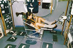
Astronauts who spend long periods of time in orbit periodically measure their body masses as part of their health-maintenance programs. On earth, it is simple to measure body weight W with a scale and convert it to mass m using the acceleration due to gravity, since W=mg. However, this procedure does not work in orbit, because both the scale and the astronaut are in free-fall and cannot press against each other (see Conceptual Example 12 in Chapter 5). Instead, astronauts use a body mass measurement device, as Figure 10.15 illustrates. This device consists of a spring-mounted chair in which the astronaut sits. The chair is then started oscillating in simple harmonic motion. The period of the motion is measured electronically and is automatically converted into a value of the astronaut’s mass, after the mass of the chair is taken into account. The spring used in one such device has a spring constant of 606 N/m, and the mass of the chair is 12.0 kg. The measured oscillation period is 2.41 s. Find the mass of the astronaut.
 | | Figure 10.15
Astronaut Tamara Jernigan uses a body mass measurement device to measure her mass while in orbit. (Courtesy NASA.) |
|
Reasoning
The relation  (Equation 10.11) can be solved for the mass m in terms of the spring constant k and the angular frequency w. The spring constant is known. Although the angular frequency is not known, it can be related to the given oscillation period of T=2.41 s by using w=2p/T (Equation 10.4). The mass calculated using Equation 10.11 is the total mass of the astronaut and the chair, so that it will be necessary to subtract the mass of the chair to obtain the mass of the astronaut. (Equation 10.11) can be solved for the mass m in terms of the spring constant k and the angular frequency w. The spring constant is known. Although the angular frequency is not known, it can be related to the given oscillation period of T=2.41 s by using w=2p/T (Equation 10.4). The mass calculated using Equation 10.11 is the total mass of the astronaut and the chair, so that it will be necessary to subtract the mass of the chair to obtain the mass of the astronaut.
Solution
Using Equations 10.11 and 10.4 gives
Solving for the mass m, we find that
Accounting for the 12.0-kg mass of the chair reveals that the mass of the astronaut is
|
 |
Example 6 indicates that the mass of the vibrating object influences the frequency of simple harmonic motion. Electronic sensors are being developed that take advantage of this effect in detecting and measuring small amounts of chemicals. These sensors utilize tiny quartz crystals that vibrate when an electric current passes through them. If the crystal is coated with a substance that absorbs a particular chemical, then its mass increases as the chemical is absorbed and, according to the relation  (Equations 10.6 and 10.11), the frequency of the simple harmonic motion decreases. The change in frequency is detected electronically, and the sensor is calibrated to give the mass of the absorbed chemical.
| Check Your Understanding 2 |
|
|
The drawing shows plots of the displacement x versus the time t for three objects undergoing simple harmonic motion. Which object, I, II, or III, has the greatest maximum velocity?
Background:
The amplitude, period, frequency, and maximum speed of simple harmonic motion hold the key to answering this question.
For similar questions (including calculational counterparts), consult Self-Assessment Test 10.1. The test is described next.
|
|
|
| Self-Assessment Test 10.1 |
|
|
Test your understanding of the material in Sections 10.1 and 10.2:
·The Restoring Force of an Ideal Spring · Simple Harmonic Motion
|
|
|
|
| Copyright © 2000-2003 by John Wiley & Sons, Inc. or related companies. All rights reserved. |


 (
( .
.