10.1.
The Ideal Spring and Simple Harmonic Motion
Springs are familiar objects that have many applications, ranging from push-button switches on electronic components, to automobile suspension systems, to mattresses. They are useful because they can be stretched or compressed. For example, the top drawing in Figure 10.1 shows a spring being stretched. Here a hand applies a pulling force FApplied to the spring. In response, the spring stretches and undergoes a displacement of x from its original, or “unstrained,” length. The bottom drawing in Figure 10.1 illustrates the spring being compressed. Now the hand applies a pushing force to the spring, and it again undergoes a displacement from its unstrained length.
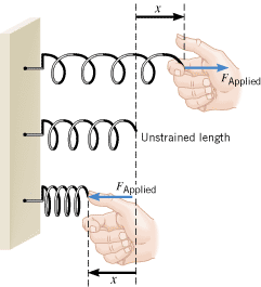 | | Figure 10.1
An ideal spring obeys the equation F
Applied
=
kx, where F
Applied is the force applied to the spring, x is the displacement of the spring from its unstrained length, and k is the spring constant. |
|
Experiment reveals that for relatively small displacements, the force FApplied required to stretch or compress a spring is directly proportional to the displacement x, or FApplied

 x. As is customary, this proportionality may be converted into an equation by introducing a proportionality constant k:
 | (10.1) |  |
The constant k is called the spring constant, and Equation 10.1 shows that it has the dimensions of force per unit length (N/m). A spring that behaves according to  is said to be an ideal spring. Example 1 illustrates one application of such a spring.
| Example 1 A Tire Pressure Gauge |
 |
|
In a tire pressure gauge, the air in the tire pushes against a plunger attached to a spring when the gauge is pressed against the tire valve, as in Figure 10.2. Suppose the spring constant of the spring is k = = 320 N/m and the bar indicator of the gauge extends 2.0 cm when the gauge is pressed against the tire valve. What force does the air in the tire apply to the spring? 320 N/m and the bar indicator of the gauge extends 2.0 cm when the gauge is pressed against the tire valve. What force does the air in the tire apply to the spring?
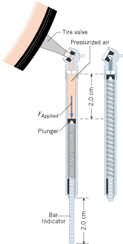 | | Figure 10.2
In a tire pressure gauge, the pressurized air from the tire exerts a force F
Applied that compresses a spring. |
|
Reasoning
We assume that the spring is an ideal spring, so that the relation  is obeyed. The spring constant k is known, as is the displacement x. Therefore, we can determine the force applied to the spring. is obeyed. The spring constant k is known, as is the displacement x. Therefore, we can determine the force applied to the spring.
Solution
The force needed to compress the spring is given by Equation 10.1 as
Thus, the exposed length of the bar indicator indicates the force that the air pressure in the tire exerts on the spring. We will see later that pressure is force per unit area, so force is pressure times area. Since the area of the plunger surface is fixed, the bar indicator can be marked in units of pressure.
|
 |
Sometimes the spring constant k is referred to as the stiffness of the spring, because a large value for k means the spring is “stiff,” in the sense that a large force is required to stretch or compress it. Conceptual Example 2 examines what happens to the stiffness of a spring when the spring is cut into two shorter pieces.
| Conceptual Example 2 Are Shorter Springs Stiffer Springs? |
 |
|
Figure 10.3a shows a 10-coil spring that has a spring constant k. If this spring is cut in half, so there are two 5-coil springs, what is the spring constant of each of the smaller springs?
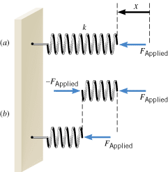 | | Figure 10.3
(a) The 10-coil spring has a spring constant k. The applied force is F
Applied, and the displacement of the spring from its unstrained length is x. (b) The spring in part a is divided in half, so that the forces acting on the two 5-coil springs can be analyzed. |
|
Reasoning and Solution It is tempting to say that each 5-coil spring has a spring constant of ½k or one-half the value for the 10-coil spring. However, the spring constant of each 5-coil spring is, in fact, 2k. Here’s the logic. When a force FApplied is applied to the spring, the displacement of the spring from its unstrained length is x, as Figure 10.3a illustrates. Now consider part b of the drawing, which shows the spring divided in half between the fifth and sixth coil (counting from the right). The spring is in equilibrium, so that the net force acting on the right half (coils 1-5) must be zero. Thus, as part b shows, a force of –FApplied must act on coil 5 in order to balance the force FApplied that acts on coil 1. It is the adjacent coil 6 that exerts the force –FApplied on coil 5, and Newton’s action-reaction law now comes into play. It tells us that coil 5, in response, exerts an oppositely directed force of equal magnitude on coil 6. In other words, the force FApplied is also exerted on the left half of the spring, as part b also indicates. As a result, the left half compresses by an amount that is one-half the displacement x experienced by the 10-coil spring. In summary, we have a 10-coil spring for which the force FApplied causes a displacement x and a 5-coil spring for which the same force causes a displacement ½x. We conclude, then, that the 5-coil spring must be twice as stiff as the 10-coil spring. When the 10-coil spring is cut in half, the spring constant of each resulting 5-coil spring is 2k. In general, the spring constant is inversely proportional to the number of coils in the spring, so shorter springs are stiffer springs, all other things being equal.
Related Homework:
Problems 8, 16
|
 |
To stretch or compress a spring, a force must be applied to it. In accord with Newton’s third law, the spring exerts an oppositely directed force of equal magnitude. This reaction force is applied by the spring to the agent that does the pulling or pushing. In other words, the reaction force is applied to the object attached to the spring. The reaction force is also called a “restoring force,” for a reason that will be clarified shortly. The restoring force of an ideal spring is obtained from the relation FApplied =
= kx by including the minus sign required by Newton’s action-reaction law, as indicated in Equation 10.2.
| HOOKE’S LAW RESTORING FORCE OF AN IDEAL SPRING |
|
The restoring force of an ideal spring is
 | (10.2) |  |
where k is the spring constant and x is the displacement of the spring from its unstrained length. The minus sign indicates that the restoring force always points in a direction opposite to the displacement of the spring.
|
 CONCEPTS AT A GLANCE In Chapter 4 we encountered four types of forces: the gravitational force, the normal force, frictional forces, and the tension force. The Concepts-at-a-Glance chart in Figure 4.9 illustrates that these forces can contribute to the net external force, which Newton’s second law relates to the mass and acceleration of an object. The restoring force of a spring can also contribute to the net external force, as the Concepts-at-a-Glance chart in Figure 10.4 indicates. Except for this force, this chart is identical to that in Figure 4.9. Once again, we see the unifying theme of Newton’s second law, in that individual forces contribute to the net force, which, in turn, is responsible for the acceleration. Newton’s second law plays a central role in describing the motion of objects attached to springs.
|
| Figure 10.4
CONCEPTS AT A GLANCE The restoring force of a spring may contribute to the net external force SF that acts on an object. According to Newton’s second law, the resulting acceleration a is directly proportional to the net force. The springs on his feet, his weight, and the normal force from the ground provide the net force that causes this fellow’s bouncing motion. (© Windsor & Wiehahn/Stone/Getty Images) |
|
Figure 10.5 helps to explain why the phrase “restoring force” is used. In the picture, an object of mass m is attached to a spring on a frictionless table. In part A, the spring has been stretched to the right, so it exerts the leftward-pointing force F. When the object is released, this force pulls it to the left, restoring it toward its equilibrium position. However, consistent with Newton’s first law, the moving object has inertia and coasts beyond the equilibrium position, compressing the spring as in part B. The force exerted by the spring now points to the right and, after bringing the object to a momentary halt, acts to restore the object to its equilibrium position. But the object’s inertia again carries it beyond the equilibrium position, this time stretching the spring and leading to the restoring force F shown in part C. The back-and-forth motion illustrated in the drawing then repeats itself, continuing forever, since no friction acts on the object or the spring.
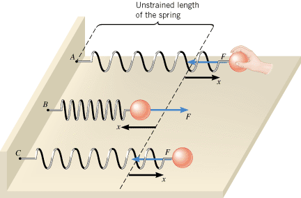 | | Figure 10.5
The restoring force (see blue arrows) produced by an ideal spring always points opposite to the displacement (see black arrows) of the spring and leads to a back-and-forth motion of the object. |
|
When the restoring force has the mathematical form given by F =
= –kx, the type of friction-free motion illustrated in Figure 10.5 is designated as “simple harmonic motion.” By attaching a pen to the object and moving a strip of paper past it at a steady rate, we can record the position of the vibrating object as time passes. Figure 10.6 illustrates the resulting graphical record of simple harmonic motion. The maximum excursion from equilibrium is the amplitude A of the motion. The shape of this graph is characteristic of simple harmonic motion and is called “sinusoidal,” because it has the shape of a trigonometric sine or cosine function.
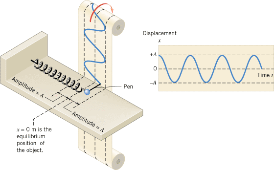 | | Figure 10.6
When an object moves in simple harmonic motion, a graph of its position as a function of time has a sinusoidal shape with an amplitude A. A pen attached to the object records the graph. |
|
| Check Your Understanding 1 |
 |
|
A 0.42-kg block is attached to the end of a horizontal ideal spring and rests on a frictionless surface. The block is pulled so that the spring stretches by 2.1 cm relative to its unstrained length. When the block is released, it moves with an acceleration of 9.0 m/s2. What is the spring constant of the spring?
Background:
The force produced by an ideal spring, acceleration, and Newton’s second law of motion play roles in this problem.
For similar questions (including conceptual counterparts), consult Self-Assessment Test 10.1. This test is described at the end of Section 10.2.
|
|
 |
The restoring force also leads to simple harmonic motion when the object is attached to a vertical spring, just as it does when the spring is horizontal. When the spring is vertical, however, the weight of the object causes the spring to stretch, and the motion occurs with respect to the equilibrium position of the object on the stretched spring, as Figure 10.7 indicates. The amount of initial stretching d0 due to the weight can be calculated by equating the weight to the magnitude of the restoring force that supports it; thus, mg =
= kd0, which gives d0
 =
= mg/k.
mg/k.
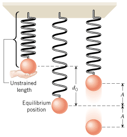 | | Figure 10.7
The weight of an object on a vertical spring stretches the spring by an amount d
0. Simple harmonic motion of amplitude A occurs with respect to the equilibrium position of the object on the stretched spring. |
|
 |
| Copyright © 2000-2003 by John Wiley & Sons, Inc. or related companies. All rights reserved. |


![]()

![]() x. As is customary, this proportionality may be converted into an equation by introducing a proportionality constant k:
x. As is customary, this proportionality may be converted into an equation by introducing a proportionality constant k:
 is said to be an ideal spring. Example 1 illustrates one application of such a spring.
![]() =
=![]() kx by including the minus sign required by Newton’s action-reaction law, as indicated in Equation 10.2.
kx by including the minus sign required by Newton’s action-reaction law, as indicated in Equation 10.2.![]() CONCEPTS AT A GLANCE In Chapter 4 we encountered four types of forces: the gravitational force, the normal force, frictional forces, and the tension force. The Concepts-at-a-Glance chart in Figure 4.9 illustrates that these forces can contribute to the net external force, which Newton’s second law relates to the mass and acceleration of an object. The restoring force of a spring can also contribute to the net external force, as the Concepts-at-a-Glance chart in Figure 10.4 indicates. Except for this force, this chart is identical to that in Figure 4.9. Once again, we see the unifying theme of Newton’s second law, in that individual forces contribute to the net force, which, in turn, is responsible for the acceleration. Newton’s second law plays a central role in describing the motion of objects attached to springs.
CONCEPTS AT A GLANCE In Chapter 4 we encountered four types of forces: the gravitational force, the normal force, frictional forces, and the tension force. The Concepts-at-a-Glance chart in Figure 4.9 illustrates that these forces can contribute to the net external force, which Newton’s second law relates to the mass and acceleration of an object. The restoring force of a spring can also contribute to the net external force, as the Concepts-at-a-Glance chart in Figure 10.4 indicates. Except for this force, this chart is identical to that in Figure 4.9. Once again, we see the unifying theme of Newton’s second law, in that individual forces contribute to the net force, which, in turn, is responsible for the acceleration. Newton’s second law plays a central role in describing the motion of objects attached to springs.
![]() =
=![]() –kx, the type of friction-free motion illustrated in Figure 10.5 is designated as “simple harmonic motion.” By attaching a pen to the object and moving a strip of paper past it at a steady rate, we can record the position of the vibrating object as time passes. Figure 10.6 illustrates the resulting graphical record of simple harmonic motion. The maximum excursion from equilibrium is the amplitude A of the motion. The shape of this graph is characteristic of simple harmonic motion and is called “sinusoidal,” because it has the shape of a trigonometric sine or cosine function.
–kx, the type of friction-free motion illustrated in Figure 10.5 is designated as “simple harmonic motion.” By attaching a pen to the object and moving a strip of paper past it at a steady rate, we can record the position of the vibrating object as time passes. Figure 10.6 illustrates the resulting graphical record of simple harmonic motion. The maximum excursion from equilibrium is the amplitude A of the motion. The shape of this graph is characteristic of simple harmonic motion and is called “sinusoidal,” because it has the shape of a trigonometric sine or cosine function.
![]() =
=![]() kd0, which gives d0
kd0, which gives d0![]() =
=![]() mg/k.
mg/k.