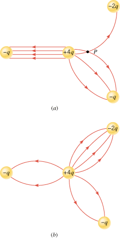
Figure 18.28a shows three negative point charges (–q, –q, and –2q) and one positive point charge (+4q), along with some electric field lines drawn between the charges. There are three things wrong with this drawing. What are they?
 |
|
Reasoning and Solution One aspect of Figure 18.28a that is incorrect is that electric field lines cross at point P. Field lines can never cross, and here’s why. An electric charge placed at P experiences a single net force due to the presence of the other charges in its environment. Therefore, there is only one value for the electric field (which is the force per unit charge) at that point. If two field lines intersected, there would be two electric fields at the point of intersection, one associated with each line. Since there can be only one value of the electric field at any point, there can be only one electric field line passing through that point.
Another mistake in Figure 18.28a is the number of electric field lines that end on the negative charges. Remember that the number of field lines leaving a positive charge or entering a negative charge is proportional to the magnitude of the charge. The –2q charge has half the magnitude of the +4q charge. Therefore, since 8 lines leave the +4q charge, 4 of them (one-half of them) must enter the –2q charge. Of the remaining 4 lines that leave the positive charge, 2 enter each of the –q charges, according to a similar line of reasoning.
The third error in Figure 18.28a is the way in which the electric field lines are drawn between the +4q charge and the –q charge at the left of the drawing. As drawn, the lines are parallel and evenly spaced. This would indicate that the electric field everywhere in this region has a constant magnitude and direction, as is the case in the central region of a parallel plate capacitor. But the electric field between the +4q and –q charges is not constant everywhere. It certainly is stronger in places close to the +4q or –q charge than it is midway between them. The field lines, therefore, should be drawn with a curved nature, similar (but not identical) to those that surround a dipole. Figure 18.28b shows more nearly correct representations of the field lines for the four charges.
Related Homework: Problems 26, 55