18.6.
The Electric Field
DEFINITION
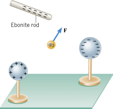
As we know, a charge can experience an electrostatic force due to the presence of other charges. For instance, the positive charge q0 in Figure 18.15 experiences a force F, which is the vector sum of the forces exerted by the charges on the rod and the two spheres. It is useful to think of q0 as a test charge for determining the extent to which the surrounding charges generate a force. However, in using a test charge, we must be careful to select one with a very small magnitude, so that it does not alter the locations of the other charges. The next example illustrates how the concept of a test charge is applied.
 | | Figure 18.15
A positive charge q0 experiences an electrostatic force F due to the surrounding charges on the ebonite rod and the two spheres. |
|
 CONCEPTS AT A GLANCE The electric force per coulomb, F/q0, calculated in Example 6(a) is one illustration of an idea that is very important in the study of electricity. The idea is called the electric field. As the Concepts-at-a-Glance chart in Figure 18.16 illustrates, the notion of an electric field emerges when we combine the electro-static force with the idea of a test charge. Equation 18.2 presents the definition of the electric field.
|
| Figure 18.16
CONCEPTS AT A GLANCE A test charge and the electrostatic force that acts on it are brought together to define the concept of an electric field. Sharks have specialized organs that can detect electric fields. In the hammerhead shark shown here, the organs are located in the wide head. (© Henry C. Wolcott III/National Geographic/Getty Images) |
|
| DEFINITION OF THE ELECTRIC FIELD |
|
The electric field E that exists at a point is the electrostatic force F experienced by a small test charge
q0 placed at that point divided by the charge itself:
 | (18.2) |  |
The electric field is a vector, and its direction is the same as the direction of the force F on a positive test charge.
SI Unit of Electric Field: newton per coulomb (N/C)
|
Equation 18.2 indicates that the unit for the electric field is that of force divided by charge, which is a newton/coulomb (N/C) in SI units.
It is the surrounding charges that create an electric field at a given point. Any positive or negative charge placed at the point interacts with the field and, as a result, experiences a force, as the next example indicates.
| Example 7 Electric Field Leads to a Force |
At a particular point in space, each of the surrounding charges contributes to the net electric field that exists there. To determine the net field, it is necessary to obtain the various contributions separately and then find the vector sum of them all. Such an approach is an illustration of the principle of linear superposition, as applied to electric fields. (This principle is introduced in Section 17.1, in connection with waves.) Example 8 emphasizes the vector nature of the electric field.
| Example 8 Electric Fields Add as Vectors Do |
POINT CHARGES
A more complete understanding of the electric field concept can be gained by considering the field created by a point charge, as in the following example.
| Example 9 The Electric Field of a Point Charge |
 |
|
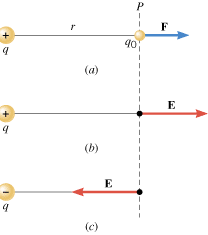
There is an isolated point charge of q = = +15 mC in a vacuum at the left in Figure 18.19a. Using a test charge of q0 +15 mC in a vacuum at the left in Figure 18.19a. Using a test charge of q0 = = +0.80 mC, determine the electric field at point P, which is 0.20 m away. +0.80 mC, determine the electric field at point P, which is 0.20 m away.
 | | Figure 18.19
(a) At location P, a positive test charge q0 experiences a repulsive force F due to the positive point charge q. (b) At P the electric field E is directed to the right. (c) If the charge q were negative rather than positive, the electric field would have the same magnitude as in (b) but point to the left. |
|
Reasoning
Following the definition of the electric field, we place the test charge q0 at point P, determine the force acting on the test charge, and then divide the force by the test charge.
Solution
Coulomb’s law (Equation 18.1), gives the magnitude of the force:
Equation 18.2 gives the magnitude of the electric field:
The electric field E points in the same direction as the force F on the positive test charge. Since the test charge experiences a force of repulsion directed to the right, the electric field vector also points to the right, as Figure 18.19b shows.
|
 |
The electric field produced by a point charge q can be obtained in general terms from Coulomb’s law. First, note that the magnitude of the force exerted by the charge q on a test charge q0 is F =
= k|q||q0|/r2. Then, divide this value by |q0| to obtain the magnitude of the field. Since |q0| is eliminated algebraically from the result, the electric field does not depend on the test charge:
 | (18.3) |  |
As in Coulomb’s law, the symbol |q| denotes the magnitude of q in Equation 18.3, without regard to whether q is positive or negative. If q is positive, then E is directed away from q, as in Figure 18.19b. On the other hand, if q is negative, then E is directed toward q, since a negative charge attracts a positive test charge. For instance, Figure 18.19c shows the electric field that would exist at P if there were a charge of –q instead of +q at the left of the drawing. Example 10 reemphasizes the fact that all the surrounding charges make a contribution to the electric field that exists at a given place.
| Example 10 The Electric Fields from Separate Charges May Cancel |
 |
|
Two positive point charges, q1 = = +16 mC and q2 +16 mC and q2 = = +4.0 mC, are separated in a vacuum by a distance of 3.0 m, as Figure 18.20 illustrates. Find the spot on the line between the charges where the net electric field is zero. +4.0 mC, are separated in a vacuum by a distance of 3.0 m, as Figure 18.20 illustrates. Find the spot on the line between the charges where the net electric field is zero.
 | | Figure 18.20
The two point charges q1 and q2 create electric fields E1 and E2 that cancel at a location P on the line between the charges. |
|
Reasoning
Between the charges the two field contributions have opposite directions, and the net electric field is zero at the place where the magnitude of E1 equals that of E2. However, since q2 is smaller than q1, this location must be closer to q2, in order that the field of the smaller charge can balance the field of the larger charge. In the drawing, the cancellation spot is labeled P, and its distance from q1 is d.
Problem solving insight
Equation 18.3 gives only the magnitude of the electric field produced by a point charge. Therefore, do not use negative numbers for the symbol |q| in this equation. |
|
Solution
At P, E1 = = E2, and using the expression E E2, and using the expression E = = k|q|/r2, we have k|q|/r2, we have
Rearranging this expression shows that 4.0(3.0 m – – d)2 d)2 = = d2. Taking the square root of each side of this equation reveals that
The plus and minus signs on the right occur because either the positive or negative root can be taken. Therefore, there are two possible values for d: +2.0 m and +6.0 m. The value +6.0 m corresponds to a location off to the right of both charges, where the magnitudes of E1 and E2 are equal, but where the directions are the same. Thus, E1 and E2 do not cancel at this spot. The other value for d corresponds to the location shown in the drawing and is the zero-field location: d2. Taking the square root of each side of this equation reveals that
The plus and minus signs on the right occur because either the positive or negative root can be taken. Therefore, there are two possible values for d: +2.0 m and +6.0 m. The value +6.0 m corresponds to a location off to the right of both charges, where the magnitudes of E1 and E2 are equal, but where the directions are the same. Thus, E1 and E2 do not cancel at this spot. The other value for d corresponds to the location shown in the drawing and is the zero-field location:  . .
|
 |
When point charges are arranged in a symmetrical fashion, it is often possible to deduce useful information about the magnitude and direction of the electric field by taking advantage of the symmetry. Conceptual Example 11 illustrates the use of this technique.
| Conceptual Example 11 Symmetry and the Electric Field |
 |
|
Figure 18.21 shows point charges fixed to the corners of a rectangle in two different ways. The charges all have the same magnitudes, but they have different signs. Consider the net electric field at the center C of the rectangle in each case. Which field is larger?
 | | Figure 18.21
Charges of identical magnitude, but different signs, are placed at the corners of a rectangle. The charges give rise to different electric fields at the center C of the rectangle, depending on the signs of the charges. |
|
Reasoning and Solution In Figure 18.21a, the charges at corners 1 and 3 are both +q. The positive charge at corner 1 produces an electric field at C that points toward corner 3. In contrast, the positive charge at corner 3 produces an electric field at C that points toward corner 1. Thus, the two fields have opposite directions. The magnitudes of the fields are identical because the charges have the same magnitude and are equally far from the center. Therefore, the fields from the two positive charges cancel.
Now, let’s look at the electric field produced by the charges on corners 2 and 4 in Figure 18.21a. The electric field due to the negative charge at corner 2 points toward corner 2, and the field due to the positive charge at corner 4 points the same way. Furthermore, the magnitudes of these fields are equal because each charge has the same magnitude and is located at the same distance from the center of the rectangle. As a result, the two fields combine to give the net electric field E24 shown in the drawing.
In Figure 18.21b, the charges on corners 2 and 4 are identical to those in part a of the drawing, so this pair gives rise to the electric field labeled E24. The charges on corners 1 and 3 are identical to those on corners 2 and 4, so they give rise to an electric field labeled E13, which has the same magnitude as E24. The net electric field E is the vector sum of E24 and E13 and is also shown in the drawing. Clearly, this sum is greater than E24 alone. Therefore, the net field in part b is larger than that in part a.
Related Homework:
Conceptual Question 12
, Problem 34
|
 |
THE PARALLEL PLATE CAPACITOR
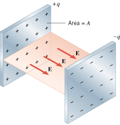
Equation 18.3, which gives the electric field of a point charge, is a very useful result. With the aid of integral calculus, this equation can be applied in a variety of situations where point charges are distributed over one or more surfaces. One such example that has considerable practical importance is the parallel plate capacitor. As Figure 18.22 shows, this device consists of two parallel metal plates, each with area A. A charge +q is spread uniformly over one plate, while a charge –q is spread uniformly over the other plate. In the region between the plates and away from the edges, the electric field points from the positive plate toward the negative plate and is perpendicular to both. Using Gauss’ law (see Section 18.9), it can be shown that the electric field has a magnitude of
 | (18.4) |  |
where e0 is the permittivity of free space. In this expression the Greek symbol sigma (s) denotes the charge per unit area (s =
= q/A) and is sometimes called the charge density. Except in the region near the edges, the field has the same value at all places between the plates. The field does not depend on the distance from the charges, in distinct contrast to the field created by an isolated point charge.
 | | Figure 18.22
A parallel plate capacitor. |
|
| Check Your Understanding 3 |
 |
|
A positive point charge +q is fixed in position at the center of a square, as the drawing shows. A second point charge is fixed to either corner B, corner C, or corner D. The net electric field at corner A is zero. (a) At which corner is the second charge located? (b) Is the second charge positive or negative? (c) Does the second charge have a greater, (a) smaller, or the same magnitude as the charge at the center?
Background:
The electric field is a vector quantity. Its magnitude and direction depend on the magnitudes and algebraic signs of the charges that create it.
For similar questions (including calculational counterparts), consult Self-Assessment Test 18.2, which is described at the end of Section 18.9.
|
|
 |
 |
| Copyright © 2000-2003 by John Wiley & Sons, Inc. or related companies. All rights reserved. |


![]() CONCEPTS AT A GLANCE The electric force per coulomb, F/q0, calculated in Example 6(a) is one illustration of an idea that is very important in the study of electricity. The idea is called the electric field. As the Concepts-at-a-Glance chart in Figure 18.16 illustrates, the notion of an electric field emerges when we combine the electro-static force with the idea of a test charge. Equation 18.2 presents the definition of the electric field.
CONCEPTS AT A GLANCE The electric force per coulomb, F/q0, calculated in Example 6(a) is one illustration of an idea that is very important in the study of electricity. The idea is called the electric field. As the Concepts-at-a-Glance chart in Figure 18.16 illustrates, the notion of an electric field emerges when we combine the electro-static force with the idea of a test charge. Equation 18.2 presents the definition of the electric field.![]() =
=![]() k|q||q0|/r2. Then, divide this value by |q0| to obtain the magnitude of the field. Since |q0| is eliminated algebraically from the result, the electric field does not depend on the test charge:
k|q||q0|/r2. Then, divide this value by |q0| to obtain the magnitude of the field. Since |q0| is eliminated algebraically from the result, the electric field does not depend on the test charge:
 .
.

![]() =
=![]() q/A) and is sometimes called the charge density. Except in the region near the edges, the field has the same value at all places between the plates. The field does not depend on the distance from the charges, in distinct contrast to the field created by an isolated point charge.
q/A) and is sometimes called the charge density. Except in the region near the edges, the field has the same value at all places between the plates. The field does not depend on the distance from the charges, in distinct contrast to the field created by an isolated point charge.