|
The Motion of the Center of Mass |
 |
Yet in the Energy Principle the force of the floor does no work on the person, because the displacement of the point of application
of this force is zero (or very small, assuming that the floor bends very little). The work done on the jumper is actually
negative, because the gravitational force of the Earth pulls down as the jumper moves up, yet vCM increases. Evidently the internal energy of the jumper must decrease in order to pay for the motion of the center of mass,
since the work done by objects in the surroundings actually does negative work on the system.
In order to deal effectively with situations of this kind, in this chapter we will introduce methods for separating the motion
of the center of mass (governed by the net force) from motion
relative to the center of mass (associated with the internal energy of the system).
Although the diver's overall motion is very complex, the center of mass of the diver must move like that of a simple projectile!
We do not yet have enough tools to analyze the diver's complicated rotation and stretching relative to the center of mass,
yet we can analyze the motion of the center of mass by applying the Momentum Principle.
Center of Mass
We briefly review what was established in Chapter 3 about the concept of the center of mass of a multiparticle system. It is defined as a weighted average of the positions of
all the atoms that make up the chosen system (Figure 9.2), with
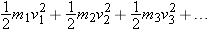
Mtotal =
m1 +
m2 +
m3 + … :
Rearrange the definition above as follows:
Differentiate this equation with respect to time (

), in the case where
Mtotal is not changing:
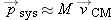
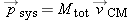
Center of Mass of Several Large Objects
For each of the large objects we have an equation for its center of mass of the form

, and so on.
We group terms in the calculation of the location of the center of mass of the total system:
This looks just like the equation for finding the center of mass of a bunch of atoms, except that the

vectors refer to the centers of mass of large objects.
| 9.X.1 |
Three uniform-density spheres are positioned as follows:
|
|
|
A 3 kg sphere is centered at (10, 20, −5) m.
|
|
|
|
A 5 kg sphere is centered at (4, −15, 8) m.
|
|
|
|
A 6 kg sphere is centered at (−7, 10, 9) m.
|
|
What is the location of the center of mass of this three-sphere system?
Answer:
(0.57, 3.21, 5.64) m
|
|
|
|
|
| 9.X.2 |
Relative to an origin at the center of the Earth, where is the center of mass of the Earth–Moon system? The mass of the Earth
is 6 × 1024 kg, the mass of the Moon is 7 × 10²² kg, and the distance from the center of the Earth to the center of the Moon is 4 × 10⁸ m. The radius of the Earth is 6400 km. One can show that the Earth and Moon orbit each other around this center of mass.
Answer:
4.6 × 10⁶ m = 4600 km (so it is inside the Earth)
|
|
|
|
|
|
|
|
|
Application: An Ice Skater Pushes Off from a Wall
The Momentum Principle is always valid, but applying it can produce some nonintuitive predictions. Consider a woman on ice
skates who pushes on a wall with a nearly constant contact force to the left of magnitude
FN (normal to the wall in Figure 9.4). By the reciprocity of electric interatomic forces, the wall exerts a force of magnitude
FN to the right on the skater. As a result, she moves backward with increasing speed. Her center of mass is marked on each frame
of the following sequence:
The intriguing aspect of this simple result is that during the time that the wall exerts a force
FN on the skater's hand, her hand does not move! (Note that the work done by the force exerted by the wall is zero; more about
this later.) The place where the force
FN is applied is very far away from the mathematical point (the center of mass) whose rate of change of speed we predict. It
is only because the electric interactions between neighboring atoms in the skater's body obey the principle of reciprocity
(Newton's third law) that these internal forces cancel and lead to a simple prediction for the motion of the center of mass:
Note that as the skater straightens her arms, the location in her body of the center of mass shifts toward her hands a little;
it is not a point fixed at some place in her body. The motion that we predict is the motion of this mathematical center of
mass point.
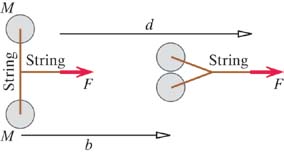
Application: Pull on Two Hockey Pucks
The pucks have the same mass
M. Assume that friction with the ice rink is negligible. It would be reasonable to suppose that it would make a difference
where you attach the string to the puck.
Both pucks are subjected to exactly the same external force, so their centers of mass must move in exactly the same way. After
a short time Δt, the momentum of the center of mass must be FTΔt, in the direction of the string, for both pucks. Despite the fact that one puck is pulled from the side, the change in momentum
of its center of mass must be in the direction of the net external force, so it cannot acquire a momentum component at right
angles to that force. Doesn't this seem a bit odd? For example, one might have expected the second puck to have some kind
of sideways motion.
| 9.X.3 |
Is there any difference at all in the motion of the two pucks? Think about the motion of your hands at the other ends of the
strings. Which hand does more work? Which puck has more energy? In what forms? Does the Momentum Principle for the motion
of the center of mass predict all the details of the motion of both pucks?
Answer:
The puck with the string wound around it is rotating and so has additional kinetic energy. You have to pull farther, by the
amount of string that unwinds, so you do more work, which corresponds to this puck having more kinetic energy. The Momentum
Principle for the motion of the center of mass tells us nothing about the rotational aspects of the motion.
|
|
|
|
|
| 9.X.4 |
Answer:
6 kg · m/s/s to the right; 20 m/s2
|
|
|
|
|
|
|
|
|
|
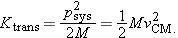
Separation of Multiparticle System Energy |
|
We have seen that we can predict the motion of a multiparticle object by treating it as if all its mass were concentrated
at the center of mass, acted upon by a force that is the (vector) sum of all the external forces acting on the object. In
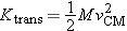
many situations we find that the energy of a multiparticle system can also be analyzed simply, by dividing the kinetic energy
of the system into two parts: the translational kinetic energy,
Ktrans, and
Krel, the kinetic energy relative to the center of mass.
Krel includes the kinetic energy associated with rotation of the object and the kinetic energy associated with vibration of the
object.
This split of the total kinetic energy into different parts sounds plausible. A formal derivation of this result is given
in Section 9.8 at the end of this chapter.
Translational Kinetic Energy
In physics, the word “translate” means “move from one location to another.” Translational motion is the ordinary kind of motion
we have studied most so far. The translational motion of a macroscopic object is described by

, the velocity of the object's center of mass. We use the term “translate” here in order to distinguish between translational
motion, in which the center of mass of a system moves from one location to another, and other kinds of motion such as rotation
and vibration, in which parts of a system move relative to the center of mass.
Vibrational Energy
The same reasoning applies to the motion of a hot block of metal. In addition to its translational kinetic energy

there is vibrational kinetic and elastic energy of the atoms around their equilibrium positions, which we call thermal energy,
with more thermal energy if the block's temperature is higher.
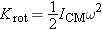
Rotational Kinetic Energy
Just as a vibrating object has kinetic energy associated with vibration, even if its center of mass is at rest, so a rotating
object has kinetic energy associated with rotation, even if its center of mass is at rest.
As an example, suppose that you spin a bicycle wheel on its axis, and hold the axle stationary, as in Figure 9.11. The spinning wheel has some kinetic energy
Krel, which in this case we will call
Krot, because the atoms are moving in rotational motion relative to the center of mass. Almost all of the mass
M of the wheel is in the rim, so if the rim is traveling at a (tangential) speed
vrel, the kinetic energy of the wheel is approximately
(This isn't exact, because there is some mass in the spokes, and the atoms in the spokes are moving at speeds smaller than
vrel.)
|
|
|
|
|
| Figure 9.11 |
A bicycle wheel spinning on its axle, which is at rest. Atoms in the rim have a speed vrel relative to the center of mass.
|
|
|
|
|
In Section 9.3 we will see how to calculate the rotational kinetic energy of other kinds of rotating objects.
Rotation, Vibration, and Translation
Find the kinetic energy in terms of these two momentum components:
Therefore the kinetic energy relative to the center of mass splits into two terms, rotational energy and vibrational energy:
The total energy of a translating, rotating, vibrating oxygen molecule can be written like this:
where
If the object can fly apart into separate pieces, we might call the kinetic energy relative to the center of mass Kexplosion! For example, a fireworks rocket has translational kinetic that doesn't change from just before to just after its explosion,
and the pieces move at high speeds relative to the center of mass of the rocket. These large kinetic energies relative to
the center of mass come from the chemical energy used up in the explosion.
Why Separating Kinetic Energy Is Simpler
If we do not separate kinetic energy into
Ktrans +
Krel, adding up the kinetic energies of all the particles in a system may be a very complex task. Consider the bicycle wheel shown
in Figure 9.13. The fact that this wheel is both translating to the right, and also spinning on its axis, means that particles at different
locations in the wheel have quite different speeds. For example, an atom at the bottom of the wheel is actually moving at
a speed less than
vCM, while an atom at the top of the wheel is moving at a speed greater than
vCM. In order to calculate the kinetic energy of the whole system, we would have to figure out the instantaneous speed of each
constituent particle!
|
|
|
|
|
| Figure 9.13 |
The velocity of an atom in the rim is the vector sum of the center-of-mass velocity and the velocity relative to the center
of mass.
|
|
|
|
|
Gravitational Energy of a Multiparticle System
In previous chapters we have calculated the gravitational potential energy of a system consisting of the Earth and a multiparticle
object simply by treating the object as if all its mass were concentrated at a single point (its center of mass). Why is this
correct?
Consider the gravitational energy of a block of mass
M and the Earth, near the Earth's surface. The gravitational energy associated with the interaction of the Earth with the
i-th atom in the block is
migyi (Figure 9.14).
|
|
|
|
|
| Figure 9.14 |
The i-th atom in the block is a distance yi from the Earth's surface.
|
|
|
|
|
We can calculate the total gravitational energy by adding up the gravitational energy associated with the interaction of each
of the
N atoms with the Earth:
However, the last expression in parentheses appears in the calculation of the
y component of the location of the center of mass:
Therefore for a block made up of many atoms, near the Earth's surface, we have this:
In other words, the gravitational energy of a block of material and the Earth, near the Earth's surface, can be evaluated
as though the block were a tiny particle of mass M located at the center of mass of the block.
This simple equation is not valid if the object is so large that the strength of the gravitational field is significantly
different at different locations in the object, but in that case
mg would not be a good approximation for the gravitational force, nor
mgy a good approximation for the gravitational energy associated with each atom.
This is a good approximation, because the spacecraft is very small compared to the distances to the Earth and Moon, so the
gravitational force on each atom is nearly the same.
|
Rotational Kinetic Energy |
|
Angular speed, normally denoted by ω (lowercase Greek omega), is a measure of how fast something is rotating. If an object
makes one complete turn of 360 degrees (2π radians) in a time
T, we say that its angular speed is ω = 2
π/T radians per second. The time
T is called the period.
An atom rotating at a constant rate around an axis at a distance
r from the axis goes a distance of the circumference 2
πr in the period
T, so the speed
v of the atom can be expressed in terms of the angular speed:
We measure angular speed ω in the “natural” units of radians per second rather than degrees per second, because the fundamental
geometrical relationship between angle and arc length (arc length =
rθ) is valid only if the angle
θ is measured in radians.
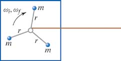
The kinetic energy of the system shown in Figure 9.17, which is a rotating rigid object, is
. Since the speed of each mass is

(where
r
is the perpendicular distance of the mass from the axis of rotation), we can write the rotational kinetic energy like this:
The quantity in brackets is called the “moment of inertia” and is usually denoted by the letter
I:
|
|
|
|
|
| Figure 9.17 |
A case of rigid rotation about an axis with angular speed ω. Note the different speeds, with vi = ωri.
|
|
|
|
|
Using this definition, we have a compact expression for rotational kinetic energy:
|
 |
|
Rotational Kinetic Energy |
|
 |
|
|
|
 |
|
 |
|
|
|
|
|
|
|
|
|
|
|
|
System: Wheel and string
Surroundings: Your hand, axle, Earth
Free-body diagram: Figure 9.20
Principle: Energy Principle
What is the moment of inertia  ? Group this sum into a part that includes just the atoms of the inner ring and another part that includes just the atoms
of the outer ring:
This is a general result: The moment of inertia of a composite object is the sum of the moments of inertia of the individual
pieces, because we have to add up all the contributions of all the atoms. We already determined that the moment of inertia
of a ring is MR2 (all the atoms are at the same perpendicular distance R from the center), so the moment of inertia of this wheel is
We need to convert revolutions per second into radians per second:
You, the Earth, and the axle all exert forces on the system. How much work does the Earth do? Zero, because the center of
mass of the wheel doesn't move. How much work does the axle do? If there is negligible friction between the axle and the wheel,
the axle does no work, because there is no displacement of the axle's force. Therefore only you do work, and the work that
you do is
|
|
|
|
|
|
|
|
Further Discussion
Although the outer ring has a smaller mass than the inner ring, the outer ring has a larger moment of inertia because its
radius is 2.5 times as big, so the factor
R2 is 6.25 times as big. Applying the Momentum Principle to the wheel, we see that the three forces must add up to zero, because
the momentum

of the wheel isn't changing.
| 9.X.5 |
If an object has a moment of inertia 19 kg · m2 and rotates with an angular speed of 70 radians/s, what is its rotational kinetic energy?
Answer:
4.7 × 10⁴ J
|
|
|
|
|
|
|
|
|
Moment of Inertia of a Thin Rod
We've seen how to calculate the moment of inertia in a few simple special cases. We will calculate the moment of inertia of
a long thin rod about its center to illustrate a more general technique. Consider a rod of mass
M and length
L whose thickness is small compared to its length, and that rotates around an axis perpendicular to the page (Figure 9.22). The density of the rod is the same everywhere (“uniform density”); every centimeter along the rod has the same mass. We
need to evaluate the sum
for all the atoms in the rod.
|
|
|
|
|
| Figure 9.22 |
A uniform-density rod of length L rotates around an axis perpendicular to the page. We divide it into short slices and choose the origin to be at the center
of the rod, with the x axis lying along the rod.
|
|
|
|
|
Divide into Small Slices
As shown in Figure 9.22, we've chosen the origin of our axes to be at the center of the rod, and we've oriented the x axis to lie along the rod. We mentally divide the rod into N small slices of equal length Δx = L/N. Each slice has a mass ΔM = M/N, because the rod's density is the same everywhere. We need to add up all the contributions to I made by all the slices.
The Mass of one Slice
Concentrate on one representative slice, whose center in Figure 9.22 is located at (
xn, 0, 0) and whose mass is Δ
M =
M/N. Since Δ
x =
L/N,
Another way to see this is that Δ
x/L is the fraction of the rod contained in this slice of length Δ
x, so the mass of this slice should be
M(Δ
x/L).
The Contribution of one Slice
Now we're able to write down an expression for the contribution Δ
I to the moment of inertia
I of the rod that is made by this one representative slice of the rod. We make the approximation that all the atoms of this
slice are approximately the same perpendicular distance
r ≈
xn from the center of the rod:
Adding up the Contributions
We need to add up all such contributions by all such slices. One way to do this is numerically, by dividing the rod into,
say,
N = 50 slices, evaluating (
M/L)
x2nΔ
x for each slice, and adding up all the contributions (Σ means “summation”):
The Finite Sum Becomes A Definite Integral
In some cases, including this case of a long thin rod, it is possible to use integral calculus to evaluate the summation.
In the limit of large
N (which means small Δ
x), the sum becomes an integral (the ∫ symbol is a distorted
S for Summation). The finite slice length Δ
x turns into the infinitesimal quantity
dx, and the sum from 1 to
N turns into a definite integral with lower and upper limits on
x (
xi and
xf):
The Limits of Integration
Since we put the origin at the center of the rod in Figure 9.22, the lower limit
xi is −
L/2 and the upper limit
xf is +
L/2:
You should find that
I = (1/12)
ML2. If you are unable to get this result, review integral calculus and make sure that you can do this kind of integral.
Because it is easy to make a mistake in this kind of calculation, it is important to check whether the results are reasonable.
First, are the units correct? Yes, (1/12)
ML2 has units of kg · m
2, which are units of moment of inertia. Also, if we double the mass
M,
I doubles, which makes sense, and if we double the length
L,
I gets four times bigger, which also makes sense given the factors of

that appear in the definition of moment of inertia.
We made the approximation that all the atoms in one slice had the same perpendicular distance xn from the center of the rod. If the rod is thick, this isn't a valid approximation, even in the limit of infinitesimally short
slices, because now those short slices are thick.
| 9.X.7 |
A thin uniform-density rod whose mass is 1.2 kg and whose length is 0.7 m rotates around an axis perpendicular to the rod,
with angular speed 50 radians/s. Its center moves with a speed of 8 m/s.
|
|
(a)
|
What is its rotational kinetic energy?
|
|
|
(b)
|
What is its total kinetic energy?
|
|
Answer:
|
|
(a)
|
61.3 J;
|
|
|
(b)
|
99.7 J
|
|
|
|
|
|
|
|
|
|
|
Moments of Inertia of Simple Shapes
A thin rod is like a cylinder with radius
R ≈ 0, in which case the moment of inertia for rotation about an axis perpendicular to the rod reduces to

.
| 9.X.8 |
A uniform-density disk whose mass is 10 kg and radius is 0.4m makes one complete rotation every 0.2 s. What is the rotational
kinetic energy of the disk?
Answer:
395 J
|
|
|
|
|
| 9.X.9 |
A uniform-density sphere whose mass is 10 kg and radius is 0.4m makes one complete rotation every 0.2 s. What is the rotational
kinetic energy of the sphere?
Answer:
316 J
|
|
|
|
|
|
|
|
|
Rigid Rotation about a Point Not the Center of Mass
We know that in general
Ktot =
Ktrans +
Krel, and in this case
Krel is just
Krot, since there is no vibration or explosion. The red line painted through the center of mass on the object in Figure 9.25 rotates with the same angular speed ω as the rod, which rotates around the axle; both the line and the object make one revolution
in the same amount of time, so the kinetic energy that is relative to the (moving) center of mass is, as usual,
.
The center of mass of the object rotates about the axle with angular speed
ω at a distance
rCM from the axle, so the speed of the center of mass (in meters per second) is
vCM = ω
rCM. Therefore we have
| 9.X.10 |
A solid uniform-density sphere is tied to a rope and moves in a circle with speed v. The distance from the center of the circle to the center of the sphere is d, the mass of the sphere is M, and the radius of the sphere is R.
|
|
(a)
|
What is the angular speed ω?
|
|
|
(b)
|
What is the rotational kinetic energy of the sphere?
|
|
|
(c)
|
What is the total kinetic energy of the sphere?
|
|
Answer:
|
|
|
|
|
|
|
|
|
|
The “Point Particle System” |
|
In analyzing the motion and energy of deformable multiparticle systems (systems whose shape can change), we encounter situations
in which it would be extremely convenient to be able to calculate only the change in the translational kinetic energy Ktrans of the system. Perhaps this might be all we are interested in, or perhaps we might wish to subtract this energy change from
the change of the total energy of the system to find out how much energy has gone into vibration or rotation. Fortunately,
it is quite simple to calculate ΔKtrans by itself.
These two different systems have the same total mass
M, and both are acted on by the same net force, so the two paths are exactly the same. The difference is that the real system
may rotate and stretch and vibrate due to the effects of the forces acting at different locations on the extended object.
In contrast, the point particle system has no rotational motion, no vibrational motion, no internal energy of any kind. All
of the forces act at the location of the point particle, and these forces don't stretch or rotate it. The only energy the
point particle system can have is translational kinetic energy, and this is exactly the same as the translational kinetic
energy of the real multiparticle system:
An analysis of the point particle system gives the translational kinetic energy of the real system. This is why the point
particle system is a useful concept. The force and energy equations for the fictitious point particle are these:
The integral is the work done on the point particle system by the net force, which acts at the location of the point itself.
In Chapter 6 we showed that starting from the Momentum Principle for a single point particle we could derive the result that the change
in the kinetic energy of the particle is equal to the work done on the particle by the net force. Here, we consider the net
force to be applied to the fictitious point particle located at the center-of-mass point, doing work to increase the kinetic
energy of the point particle. A more formal derivation of the energy equation for the point particle system may be found at
the end of this chapter.
These equations tell us about the motion of the center of mass of a multiparticle system, but they tell us nothing about the
vibration or rotation or thermal changes of the system. For a full treatment we need to combine analyses of the point particle
system with analyses of the real system.
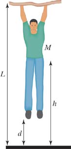
Application: Jumping Up
As an example of how to exploit the point particle system, we'll analyze
h jumping (Figure 9.28). You crouch down and then jump straight upward. We want to calculate how fast your center of mass
vCM is moving at the instant that your feet leave the floor. Let
h be the distance through which your center of mass rises in this process. Note that there is a change of shape of the system.
|
|
|
|
|
| Figure 9.28 |
As the jumper leaves the floor, the center of mass has risen h. The system changes shape.
|
|
|
|
|
Let
FN be the electric contact force that the atoms in the floor exert on the bottom of your foot, and let
M be your total mass. We don't know exactly how the floor force
FN varies with time, but to get an idea of what happens let's make the crude approximation that it is constant as long as you
are in contact with the floor (of course it falls suddenly to zero as your foot leaves the floor). Consider the different
point particle system shown in Figure 9.29, which does not change shape.
|
|
|
|
|
| Figure 9.29 |
Force diagram for your body, considered as a point particle. This system does not change shape.
|
|
|
|
|
Jumper: Point Particle System
As indicated in Figure 9.29 the net force in the upward direction is (
FN −
Mg), and the energy equation for the point particle system is
As we will see, this is not the same as the energy equation for the real system consisting of you, the jumper! The reason
FN shows up in the point particle energy equation is that it contributes to the net force and impulse, which affects the momentum
(which is related to the motion of the center of mass). The work done on the point particle system involves the net force
multiplied by the displacement of the center-of-mass point.
Jumper: Real System
There is change of kinetic energy of your moving arms and legs relative to the center of mass, decrease of chemical energy
inside you, and increase of thermal energy inside you (your temperature rises somewhat).
The floor force FN is applied to the bottom of your foot, and the contact point does not move during the entire process leading to lift-off,
so there is no work. The definition of the work done by a force involves (the parallel component of) the displacement of the
point of contact, at the place where the force is applied to the object. No displacement, no work done on you.
The energy equation for the real system (you, the jumper) looks something like the following, ignoring
Q, transfer of energy due to a temperature difference between you and the surrounding air:
The floor force
FN does not appear in the energy equation for the real system, because this force does no work (no displacement of the point
of contact;

). (The floor force does, however, appear in the energy equation for the point particle system.) As before, the gravitational
force does negative work on you.
ΔKother includes the rotation of your upper and lower legs and the swinging of your arms. ΔEthermal corresponds to the higher temperature that your body runs due to the exertion (which ultimately will lead to transfer of
energy Q out of your body into the surroundings, due to the higher temperature compared to the cooler air). ΔEchemical represents the burning of chemical energy stored in your body, in order to support this activity. None of these terms appear
in the energy equation for the point particle system, because the point particle equation deals just with the motion of the
mathematical center of mass point, which doesn't rotate or stretch or get hot. Acrucial difference is that you change shape
(legs unbend, etc.), but the point particle system doesn't.
Finding the Change in Internal Energy
Replace Δ
Ktrans in the energy equation for the real system with the value of Δ
Ktrans we found for the point particle system:
Comparison of the Point Particle and Real Energy Equations
The important thing to notice is that the energy equation for the real system and for the point particle system are quite
different. Most energy terms do not appear at all in the point particle equation, and the work that appears in the energy
equation for the real system is not the same as the work that appears in the energy equation for the point particle system.
All of these energy changes of your body are positive except for the change in chemical energy, which decreases to pay for
all the other increases.
Application: Stretching a Spring
Let's check to make certain this kind of analysis gives us a sensible answer in a simple situation. You pull on one end of
a spring (Figure 9.30) with a force
FL to the left, making a short displacement Δ
rL to the left, and you pull on the other end with an equal but opposite force
FR and equal but opposite short displacement Δ
rR. The system (the spring) changes shape. Our analysis should yield the expected result: the spring should not gain translational
kinetic energy!
|
|
|
|
|
| Figure 9.30 |
You pull on both ends of a spring with equal and opposite forces. The system (the spring) changes shape.
|
|
|
|
|
Spring: Real System
Consider the spring itself as the system.
Your left hand exerts a force through a short displacement ΔrL and does some (positive) work WL = FLΔrL cos(0°) = +FLΔrL.
Your right hand also exerts a force through a short displacement ΔrL and does some (positive) work WR = FRΔrR cos(0°) = +FRΔrR.
The total work increases the energy of the spring, in the form of spring (elastic) energy corresponding to increased stretch
of the spring. Note carefully that both hands do positive work. The energy equation for the real system undergoing this process
(the spring) is this:
Spring: Point Particle System
The net force is zero (
FR −
FL = 0). Reassuringly, the center of mass does not move. The work done on the fictitious point particle is zero, so there is
no change in the speed of the center of mass, thus no change in the translational kinetic energy
. The energy equation reduces to 0 = 0, which is certainly correct but provides no detailed information.
Comparison of the Point Particle and Real Energy Equations
The key point here is that in the real system, work is calculated by adding up the amount of work done by each force: the work done by your right hand plus the work done by your left hand. The work done by each force is the force times the actual displacement of the point of application
of that force, FLΔrL and FRΔrR, both of which are positive.
In the point particle system, however, work is calculated by first adding up all the forces to get the net force before calculating the work, and the net force is multiplied by the displacement of the center of mass. In the present
example the net force is zero, and the displacement of the center of mass is zero, so the work done on the point particle
system is zero.
Note also that the actual work done by an individual force involves the displacement of the point where the force is applied.
In contrast, work done on the point particle system involves the displacement of the center of mass point, a point that may
be very far away from any of the actual locations where the forces are applied, with a motion that is quite different from
the motion of the point of application of an individual force.
Another way of looking at the situation is that the real multiparticle system (the spring) changes shape, and there is potential
energy associated with that change of shape. The point particle system does not change shape, and there is no change in potential
energy.
The energy equation for the real system and the energy equation for the point particle system are both valid and give correct
results for any process, but they provide different kinds of information:
|
|
Real system: Information on change of total energy of system
|
|
|
Point particle system: Information on change of translational kinetic energy
|
|
The differences are what make it useful to analyze certain kinds of phenomena both ways. Note that the two energy equations
are different for this spring example because the system is deformable and changes shape, which leads to very different calculations
of the work in the two systems.
| 9.X.11 |
If a system such as a large block does not change shape (or rotate faster and faster due to tangential forces, and there are
no changes of identity or temperature), the energy equations for the real system and for the point particle system are identical.
Explain why.
Answer:
All of the applied forces act through the same displacement, which is also the displacement of the center of mass. So it makes
no difference whether you calculate the work done by each individual force and then add them up, or first add up all the forces
and then calculate the work. Also, the only energy change in such a system is the overall kinetic energy.
|
|
|
|
|
| 9.X.12 |
A runner whose mass is 50 kg accelerates from a stop to a speed of 10 m/s in 3 seconds. (A good sprinter can run 100 meters
in about 10 seconds, with an average speed of 10 m/s.)
|
|
(a)
|
What is the average horizontal component of the force that the ground exerts on the runner's shoes?
|
|
|
(b)
|
How much displacement is there of the force that acts on the sole of the runner's shoes, assuming that there is no slipping?
Therefore, how much work is done on the real system (the runner) by the force you calculated in the previous exercise? How
much work is done on the point particle system by this force?
|
|
|
(c)
|
The kinetic energy of the runner increases—what kind of energy decreases? By how much?
|
|
Answer:
|
|
(a)
|
167 N;
|
|
|
(b)
|
zero displacement, so no work done on the real system, but on the point particle system there is 2500 J of work done;
|
|
|
(c)
|
internal energy (especially chemical energy) decreases by 2500 J
|
|
|
|
|
|
|
|
|
|
|
|
Analyzing Point Particle and Real Systems |
|
Here is a procedure to use in analyzing the point particle and real systems.
|
|
|
Imagine crushing the real system and its forces down to a point at the center of mass of the real system, including moving
the tails of the force arrows to that point. Draw diagrams of the initial and final states, representing the point particle
system as a dot, and showing all the forces that act on the real system.
|
|
|
|
The tails of all the forces must be on the point particle itself.
|
|
|
|
Write the Energy Principle for the point particle, paying attention to the fact that each force acts through the distance
that the point particle moves, not the distance the tail of the force moves in the real system. The energy will include only the term ΔKtrans.
|
|
|
|
Draw diagrams of the initial and final states of the real system.
|
|
|
|
Draw arrows representing the forces acting on the real system. It is very important to place the tail of each arrow at the
location where that force acts on an object.
|
|
|
|
Look carefully at how far the tails of the force arrows move, from the initial state to the final state. Use this information
to calculate the work done by each force. Add up these work terms to find the work done on the real system.
|
|
|
|
Write the Energy Principle for the real system. The energy will include the term ΔKtrans but may include additional terms.
|
|
|
|
Replace ΔKtrans in the equation for the real system with the ΔKtrans you found from the equation for the point particle.
|
|
|
|
|
|
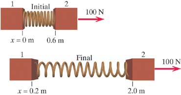
A Box Containing a Spring
A thin box in outer space contains a large ball of clay of mass M, connected to an initially relaxed spring of stiffness ks (Figure 9.32). The mass of the box and spring are negligible compared to M. The apparatus is initially at rest. Then a force of constant magnitude F is applied to the box. When the box has moved a distance b, the clay makes contact with the left side of the box and sticks there, with the spring stretched an amount s. See the diagram for distances.
|
|
(a)
|
Immediately after the clay sticks to the box, how fast is the box moving?
|
|
|
(b)
|
What is the increase in internal energy of the clay?
|
|
|
|
|
|
|
| Figure 9.32 |
A constant force acts on a thin box containing a spring and a ball of clay. The box moves a distance b, but the ball (center of mass of the system) moves only a distance b − s. Tails of arrows representing forces are drawn at the point at which they act.
|
|
|
|
|
|
|
|
|
|
|
|
|
|
|
(a)
|
Point particle system
System: Point particle of mass M
Surroundings: External object exerting force F
Initial state: Point particle at rest
Final state: Point particle moving with (unknown) speed v
Energy Principle (point particle only has Ktrans):
|
 Assume that the process takes place so quickly that there isn't time for any significant energy transfer Q due to a temperature difference between the (real) system and surroundings.
|
|
|
|
|
|
(b)
|
Real system
System: Mass, box, and spring
Surroundings: External object exerting force F
Initial state: System at rest
Final state: Box moving with (known) speed v (same as clay)
Free-body diagram: Figure 9.32
|
|
|
|
|
|
|
|
|
Further Discussion
In the energy equation for the point particle system there is nothing about the spring or thermal energy, because the point
particle system doesn't stretch or get hot. In Figure 9.33 the tail of the force vector moves a distance (b − s), moving with the point particle, so the work done on the point particle system is F(b − s).
In the real system, the tail of the force vector moves a longer distance b, so the work done on the real system is Fb. More work is done, and the extra work goes into spring potential energy and internal energy of the clay.
Good labeled diagrams of the two choices of system are extremely important, in order to determine the distances through which
forces act in the two cases. Review the procedure at the beginning of the section and see how these steps were implemented
in the example given above.
|
|
|
|
A Yo-yo
You're playing with a yo-yo of mass m on a low-mass string (Figure 9.34). You pull up on the string with a force of magnitude F, and your hand moves up a distance d. During this time the mass falls a distance h (and some of the string reels off the yo-yo's axle).
|
|
(a)
|
What is thae change in the translational kinetic energy of the yo-yo?
|
|
|
(b)
|
What is the change in the rotational kinetic energy of the yo-yo, which spins faster?
|
|
|
|
|
|
|
| Figure 9.34 |
You pull up with a force of magnitude F through a distance d on the string of a yo-yo while the yo-yo moves downward a distance h.
|
|
|
|
|
|
|
|
|
|
|
|
|
|
|
(a)
|
Point particle system System: Point particle of mass m
Surroundings: Earth and hand
Initial state: Point particle with initial translational kinetic energy
Final state: Point particle with final translational kinetic energy
Energy Principle (point particle only has Ktrans):
|
|
|
(b)
|
Real system
System: Mass and string
Surroundings: Earth and hand
Initial state: Initial rotational and translational kinetic energy
Final state: Final rotational and translational kinetic energy
Free-body diagram: Figure 9.34
|
|
|
|
|
|
|
|
|
Further Discussion
The key issue is that the distance through which the force F moves is different in the real system and the point particle system. In the real system, your hand applies an upward force
of magnitude F through an upward displacement d, doing an amount of work +Fd. However, in the other “crushed” system, where all the mass is located at the center of mass of the real system and the tails
of all the force vectors are moved to that point, the tail of the upward-pointing force vector for F is applied to the point particle as the point particle drops a distance h. Therefore the work done by the force F on the point particle is −Fh. (The work done by the Earth's force is +mgh for both systems, because this force is applied to the center of mass of the real system, which is also the center of mass
of the crushed system.) The diagrams labeled with distances are critical to calculating the work correctly for the two different
systems.
It is important to understand that the point particle or “crushed” system is a different system, with forces acting on it
that are equal in magnitude and direction to the real forces acting on the real system, but applied directly to the point
particle, so the displacements through which these forces act are different from the displacements of the real forces acting
on the real system.
In this yo-yo example the difference between the two systems is quite striking, because the work done by the force F on the real system is positive, but the work done by the force F on the point particle system is negative. (Recall that the point particle equation was derived from the Momentum Principle;
if we think about momentum, we note that the force of the hand acts to oppose the downward motion of the center of mass of
the yo-yo.)
Note also that the change of the rotational kinetic energy, Krot = F(d + h), is the same as the work that would be done to increase the purely rotational kinetic energy of a yo-yo whose axle was fixed
in space. The distance (d + h) is the length of the extra string that reels off the axle.
|
*Modeling Friction in Detail |
|
We can use what we've learned about complex systems to model the nature of sliding friction, which is a complicated phenomenon.
In Chapter 7 we described a seeming paradox involving friction: that when you drag a block at constant speed across a table it seems that
no work is done on the block, yet its temperature increases, indicating an increase in its internal energy. With the new tools
developed in this chapter, we are in a position to analyze this phenomenon in more detail and resolve the paradox.
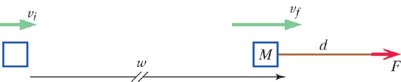
Sliding Block: Point Particle System
A key issue that we will address is the question of how much work is done on the block by the friction force f exerted by the table. One of the new tools is the energy equation for the point particle system (Figure 9.36 and Figure 9.37). You apply a force of magnitude F to the right and the table exerts a force of magnitude f to the left. (Pretend for the moment that you don't know the magnitude of the friction force f.) The change in the kinetic energy of the fictitious center-of-mass point particle is given by the product of the net force
( F − f) times the displacement d of the center-of-mass point:
Since the speed of the block is constant, Δ Ktrans = 0, so F − f = 0, which shows that the friction force is equal and opposite to the force you apply: f = F. The thermal energy does not appear in this energy equation for the point particle system, because this equation deals merely
with the motion of the (mathematical) center of mass, not with the many kinds of energy in the real system.
|
|
|
|
|
| Figure 9.36 |
The center of mass of the block moves a distance d under the influence of a net force F − f.
|
|
|
|
|
|
|
|
|
|
| Figure 9.37 |
The block considered as a point particle.
|
|
|
|
|
We also could have obtained the result f = F directly from the Momentum Principle: dpsys/dt = F − f = 0. The Momentum Principle is closely related to the energy equation for the point particle system, because both involve
the net force acting on a system and the motion of the center of mass.
Sliding Block: Real System
The energy equation for the real system of the block can be written as follows,
where Fd is the work done by you, and Wfric is the work done by the table:
where Δ Ethermal is the rise in the thermal energy of the block. We're assuming that the process takes a short enough time that there is negligible
transfer of energy Q due to a temperature difference between the system of the block and the surroundings (the table), because energy transfer
due to a temperature difference between table and block is a relatively slow process. (To remove such energy transfer as a
possible complication, we could consider a block sliding not on a table but on an identical block. Then the symmetry of the
situation is such that there cannot be any net transfer of energy due to a temperature difference into or out of the upper
block. This tactic—reducing the complexity of a model—is a useful approach to complex problems.)
Since the speed of the center of mass vCM does not change, Δ Ktrans = 0, and the energy equation reduces to
If we conclude that the friction force does an amount of work − Fd, then we would have to conclude that the thermal energy of the block doesn't change, which is absurd. The block definitely
gets hotter, indicating an increase in its thermal energy. We need to find a way around the entirely plausible but apparently
incorrect conclusion that the friction force does an amount of work − Fd.
Since the thermal energy change ΔEthermal is surely positive (the block gets hotter, not colder), the magnitude of the work done by the friction force must be less
than Fd. Since the friction force is definitely equal to F, the friction force must act through some effective distance deff that must be less than d!
Evidently the energy equation for the real system has the following form, with deff less than d:
|
|
*A Physical Model for Dry Friction |
|
How can the effective distance through which the friction force does work be less than the distance through which the block
moves? We can understand this by looking at a microscopic picture of what happens on the surfaces in contact.
Because the tooth tips can become stronger than the bulk metal due to a process called “work-hardening” (which introduces
dislocations in the otherwise regular geometrical arrangements of atoms), shearing often occurs in the weaker regions of the
teeth, away from the tip. This is a major effect when the two objects are made of the same material, and chunks of metal can
break off and embed in the other surface. Nevertheless, this wear will be ignored in the further discussion. It is in any
case a symmetrical effect for identical blocks. If the metal surfaces have oxide coatings, this can reduce the shear stress
required to break the temporary weld (which reduces the friction force) and can prevent the breaking off of chunks of metal,
if the oxide contact area is the weakest section.
This is the model of dry friction developed in a classic treatise on friction, The Friction and Lubrication of Solids, Part 1 and Part II, F. P. Bowden and D. Tabor (Oxford University Press, 1950 and 1964). The physics and chemistry of friction
continues to be an active field of research, because the effects of friction can be quite complex, and there is high practical
interest in controlling friction. A more recent textbook is Friction, Wear, Lubrication, K. C. Ludema (CRC Press, 1996).
Having briefly reviewed a basic model of dry friction, we proceed to use this model to calculate the work done by frictional
forces exerted at the contact points. The key issue is that the surface is deformable, which leads to differences in the energy
equation for the real system compared with the energy equation for the point particle system.
Actual Work Done by Friction Forces
As the top block is dragged to the right, the teeth continue to stick together for a while. Both teeth must deform as a result;
the top tooth is stretched backward, and the bottom tooth is stretched forward. In Figure 9.40 we see that when the top block has moved a distance d to the right, the point where the teeth touch each other has moved a distance of only deff, because the bottom block hasn't moved. (For two identical blocks made of the same material, on average the two teeth will
bend the same amounts, and deff will be equal to d/2.)
This is the key issue: The point of contact where the friction force is applied moves a shorter distance (deff) than the block itself moves (d). This means that the work done by the friction force is less than one might expect.
The time average of the contact forces is indeed F (as determined by the fact that the net force must be zero, F − F), but the effective displacement deff at the point of contact of the frictional force is less than the displacement of the center of mass of the upper block. For
two identical blocks we expect to find that deff = d/2. For other combinations of two materials in contact, all we know is that deff must be less than d but not necessarily equal to d/2.
Internal Energy of the Blocks
Once the weld has broken, the teeth can vibrate, as we saw in Figure 9.41. The vibration of the tooth belonging to the top block and thermal conduction upward from the hot tip into the main body
of the block contribute to the increase in the thermal energy of the upper block. Similarly, vibration and thermal conduction
in the tooth belonging to the bottom block end up as increase in the thermal energy of the bottom block.
A More Physical Picture
In Figure 9.43 we see that when the top block moves a distance d to the right the upper contact also moves a distance d, whereas the lower contact does not move at all. The frictional work is therefore (− F/2)(0) + (− F/2)( d), which is − Fd/2 = − Fdeff, so deff is equal to d/2 in the special case of two identical blocks.
|
|
|
|
|
| Figure 9.43 |
During this time interval the upper contact moves a distance d, while the lower contact does not move at all.
|
|
|
|
|
Summary of Dry Friction
The fundamental reason why the friction force can act through a distance less than d is that the block is deformable. All atoms in the top block eventually move the same distance d, but because of the stick/slip contact between the blocks the friction force F acts only for a portion of the displacement (d/2 in the special case of identical blocks). The point of contact for the friction force does not move in the same way as the
center of mass. Note again that the energy equation for the point particle system is not the same as the energy equation for
the real system if the system changes shape.
A Model-Independent Calculation of the Effective Distance
Lower block held at rest In the special case of a block sliding on an identical block we can calculate deff, independent of the particular model of the surfaces. Consider a system consisting of both blocks together (Figure 9.44). The bottom block is held stationary by applying a force to the left (to prevent it being dragged to the right). This constraining
force acts through no distance (the bottom block stands still), so this force does no work. The only work done on the two-block
system is done by you, of magnitude Fd. So the energy equation for the real two-block system is this:
Since the two blocks are identical, half of this increased thermal energy shows up in the upper block ( Fd/2), and half in the lower block ( Fd/2). We can plug this into our earlier energy equation for the upper block:
We find that the effective distance through which the friction force acts is half the distance d that the block moves: deff = d/2. This is in agreement with the model of dry friction with bending teeth that we examined earlier, but our result is a general
one that applies to any kind of model of friction surfaces for two symmetrical blocks. Bear in mind that if the blocks are
not made of the same material, deff need not be equal to d/2.
|
|
|
|
|
| Figure 9.44 |
The lower block is held at rest, while the upper block slides a distance d. Forces in the vertical direction are not shown.
|
|
|
|
|
Lubricated Friction
It is a property of simple fluid flow that fluid layers immediately adjacent to the blocks are constrained to share the motion
of the blocks. Also, for a common type of flow called “laminar” flow, the displacement profile in the oil is linear. In particular,
at the midplane the fluid moves half as far as the top block moves. As a result, as the top block is pulled a distance d to the right, the top layer of the oil is dragged along and moves a distance d to the right, the bottom layer of oil doesn't move, and the layer in the midplane (halfway between the blocks) moves a distance
d/2.
If we take as the symmetrical systems of interest the top block with the upper half of the oil and the bottom block with the
lower half of the oil, we see that the shear force between the two systems (at the midplane in the oil) acts through a distance
that is again half the displacement of the top block: deff = d/2. (Of course the magnitude of the friction force is much reduced by the lubrication, and the applied force F must be much smaller if the velocity is to be constant.)
This discussion is based on an article “Work and heat transfer in the presence of sliding friction,” by B. Sherwood and W.
Bernard, American Journal of Physics volume 52, number 11, Nov. 1984, pages 1001–1007, which in turn draws on an earlier article “Real work and pseudowork,” by
B. Sherwood, American Journal of Physics, volume 51, number 7, July 1983, pages 597–602.
|
|
*Derivation: Kinetic Energy of a Multiparticle System |
|
In this section we derive the important result that Ktot = Ktrans + Krel, where and Krel is the kinetic energy relative to the center of mass. This result sounds entirely plausible, but the formal proof is rather
difficult.
As in the case of calculating the gravitational energy of a multiparticle object, the derivation of the kinetic energy of
a multiparticle system hinges on the definition of the center of mass point of a collection of atoms. The (vector) location
of the i-th atom of the object can be expressed as the sum of two vectors, one from the origin to the center of mass  plus another from the center of mass to the i-th atom 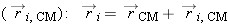 ) (Figure 9.46).
|
|
|
|
|
| Figure 9.46 |
Center of mass of a multiparticle system.
|
|
|
|
|
The kinetic energy  of the i-th atom is this, where we write  , the velocity of the i-th particle relative to the center of mass:
This can be expanded, using the fact that the magnitude squared of a vector can be written as a vector dot product,  :
Now that we have the kinetic energy of the i-th atom in terms of its velocity  relative to the center of mass, we need to add up the total kinetic energy of all the atoms. The total kinetic energy Ktot can be written in the following compact way, where Σ (Greek capital sigma) means “sum,” and the sum goes from i = 1 through i = N:
First term
The first term in this summation turns out to be the kinetic energy of a single particle of mass M, moving at the speed of the center of mass:
Second Term
The second term can be shown to be zero:
This result follows from the way that we calculate the location of the center of mass of a system:
We are measuring the location  of the i-th atom relative to the center of mass, and since the distance from the center of mass to the center of mass is of course
zero, we have
Third Term
The third term by definition is the kinetic energy of the atoms relative to the (possibly moving) center of mass:
Putting the three pieces together, we find that the total kinetic energy splits into two parts: a term associated with the
overall motion of the center of mass plus the kinetic energy relative to the center of mass:
where
|
|
*Derivation: The Point Particle Energy Equation |
|
In this chapter we showed that the energy equation for the point particle version of the system follows from the fact that
the motion of the center of mass is just like that of a point particle with the total mass of the real system and subjected
to the net force acting on the real system. Here we give a more formal derivation of this important result.
Start from the x component of the Momentum Principle for a multiparticle system whose center of mass is moving at nonrelativistic speed:
Integrate through the x displacement of the center of mass:
Switch dv and dx:
However, dxCM/dt is the x component of the center of mass velocity:
The integral on the left can be carried out:
We could repeat exactly the same argument for the y and z motions:
Note that
Moreover,
Adding the three equations together (the sum of the left sides is equal to the sum of the right sides), we have the following
equation for the translational kinetic energy of the system:
In words: the change in the translational kinetic energy of a system is equal to the integral of the net force acting through the displacement of the center of mass point.
The derivation that we have just carried out shows that although this equation looks like an energy equation, it is actually
closely related to the Momentum Principle from which it was derived. The common element is the net force.
In contrast, the actual energy equation for the real system involves the work done by each individual force through the displacement
of the point of application of that force. If the system deforms or rotates, these displacements of the individual forces
need not be the same as the displacement of the center of mass.
|
|
Summary |
|
|
Problem-Solving Techniques
Combined use of the energy equations for the real system and for the fictitious “point particle system” in analyzing complex
phenomena involving multiparticle systems.
|
|
Point particle system: Information on change of translational kinetic energy
|
|
|
Real system: Information on change of total energy
|
|
The Momentum Principle for multiparticle systems, derived from Newton's second and third laws of motion, was extended by defining
the center of mass:
(if
v <<
c, and constant mass).
Gravitational energy of multiparticle systems plus Earth, near the Earth's surface:
Kinetic energy of multiparticle systems:
where
Kinetic energy relative to center of mass can be split into two terms:
Moment of inertia about an axis of rotation:
Kinetic energy relative to center of mass:
Moments of inertia:
about center of disk, rotating around axis of cylinder
for axis passing through center of sphere.
Uniform solid cylinder of length
L, radius
R, about axis perpendicular to cylinder, through center of cylinder:
For a rigid object,

Point particle system
Sliding friction can deform the contact surfaces, with the result that the frictional force may act through a distance that
is different from the distance through which the center-of-mass point moves. As with any deformable system, the energy equations
for the real system and for the point particle system differ (though both are correct).
|
Exercises and Problems |
|
|
|
Sections 9.1, 9.2, 9.3 |
|
| 9.X.19 |
Consider a system consisting of three particles:
|
|
(a)
|
What is the total momentum of this system?
|
|
|
(b)
|
What is the velocity of the center of mass of this system?
|
|
|
(c)
|
What is the total kinetic energy of this system?
|
|
|
(d)
|
What is the translational kinetic energy of this system?
|
|
|
(e)
|
What is the kinetic energy of this system relative to the center of mass?
|
|
One way to calculate Krel is to calculate the velocity of each particle relative to the center of mass, by subtracting the centerof-mass velocity from
the particle's actual velocity to get the particle's velocity relative to the center of mass, then calculating the corresponding
kinetic energy, then adding up the three relative kinetic energies. However, there is a much simpler way to determine the
specified quantity, without having to do all those calculations; think about what you know about the relationships among the
various kinds of kinetic energy in a multiparticle system. (If you wish, you can check your result by doing the complicated
calculation just described.)
|
|
|
|
|
| 9.P.20 |
A man whose mass is 80 kg and a woman whose mass is 50 kg sit at opposite ends of a canoe 5 m long, whose mass is 30 kg.
|
|
(a)
|
Relative to the man, where is the center of mass of the system consisting of man, woman, and canoe? (Hint: Choose a specific coordinate system with a specific origin.)
|
|
|
(b)
|
Suppose that the man moves quickly to the center of the canoe and sits down there. How far does the canoe move in the water?
Explain your work and your assumptions.
|
|
|
|
|
|
|
| 9.P.21 |
Binary stars:
|
|
(a)
|
About half of the visible “stars” are actually binary star systems, two stars that orbit each other with no other objects
nearby. Describe the motion of the center of mass of a binary star system. Briefly explain your reasoning.
|
|
|
(b)
|
For a particular binary star system, telescopic observations repeated over many years show that one of the stars (whose unknown
mass we'll call M1) has a circular orbit with radius R1 = 6 × 10¹¹ m, while the other star (whose unknown mass we'll call M2) has a circular orbit of radius R2 = 9 × 10¹¹ m about the same point. Make a sketch of the orbits, and show the positions of the two stars on these orbits at some instant.
Label the two stars as to which is which, and label their orbital radii. Indicate on your sketch the location of the center
of mass of the system, and explain how you know its location, using the concepts and results of this chapter.
|
|
|
(c)
|
This double star system is observed to complete one revolution in 40 years. What are the masses of the two stars? (For comparison,
the distance from Sun to Earth is about 1.5 × 10¹¹ m, and the mass of the Sun is about 2 × 1030 kg.) This method is often used to determine the masses of stars. The mass of a star largely determines many of the other
properties of a star, which is why astrophysicists need a method for measuring the mass.
|
|
|
|
|
|
|
| 9.P.22 |
By calculating numerical quantities for a multiparticle system, one can get a concrete sense of the meaning of the relationships
 and 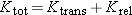 . Consider an object consisting of two balls connected by a spring, whose stiffness is 400 N/m. The object has been thrown
through the air and is rotating and vibrating as it moves. At a particular instant the spring is stretched 0.3 m, and the
two balls at the ends of the spring have the following masses and velocities:
|
|
1: 5 kg, (8, 14, 0) m/s
|
|
|
2: 3 kg, (− 5, 9, 0) m/s
|
|
|
|
(a)
|
For this system, calculate  .
|
|
|
(b)
|
Calculate  .
|
|
|
(c)
|
Calculate Ktot.
|
|
|
(d)
|
Calculate Ktrans.
|
|
|
(e)
|
Calculate Krel.
|
|
|
(f)
|
Here is a way to check your result for Krel. The velocity of a particle relative to the center of mass is calculated by subtracting from the particle's velocity. To take a simple example, if you're riding in a car that's moving with vCM,x = 20 m/s, and you throw a ball with vrel,x = 35 m/s, relative to the car, a bystander on the ground sees the ball moving with vx = 55 m/s. So  , and therefore we have  . Calculate for each mass and calculate the corresponding Krel. Compare with the result you obtained in part (e).
|
|
|
|
|
|
|
|
|
Section 9.4 |
|
| 9.X.25 |
A sphere of uniform density with mass 22 kg and radius 0.7 m is spinning, making one complete revolution every 0.5 seconds.
The center of mass of the sphere has a speed of 4 m/s.
|
|
(a)
|
What is the rotational kinetic energy of the sphere?
|
|
|
(b)
|
What is the total kinetic energy of the sphere?
|
|
|
|
|
|
|
| 9.P.28 |
The Earth is 1.5 × 10 11 m from the Sun and takes a year to make one complete orbit. It rotates on its own axis once per day. It can be treated approximately
as a uniform-density sphere of mass 6 × 10 24 kg and radius 6.4 × 10 6 m (actually, its center has higher density than the rest of the planet, and the Earth bulges out a bit at the equator). Using
this crude approximation, calculate the following:
|
|
(a)
|
What is vCM?
|
|
|
(b)
|
What is Ktrans?
|
|
|
(c)
|
What is ω, the angular speed of rotation around its own axis?
|
|
|
(d)
|
What is Krot?
|
|
|
(e)
|
What is Ktot?
|
|
|
|
|
|
|
| 9.P.29 |
Show that the moment of inertia of a disk of mass M and radius R is  . Divide the disk into narrow rings, each of radius r and width dr. The contribution to I by one of these rings is simply r2 dm, where dm is the amount of mass contained in that particular ring. The mass of any ring is the total mass times the fraction of the
total area occupied by the area of the ring. The area of this ring is approximately 2 πrdr. Use integral calculus to add up all the contributions.
|
|
|
|
|
|
|
Sections 9.5, 9.6 |
|
| 9.X.32 |
You pull straight up on the string of a yo-yo with a force
0.235 N, and while your hand is moving up a distance 0.18 m, the yo-yo moves down a distance 0.70 m. The mass of the yo-yo
is 0.025 kg, and it was initially moving downward with speed 0.5 m/s and angular speed 124 radians/s.
|
|
(a)
|
What is the increase in the translational kinetic energy of the yo-yo?
|
|
|
(b)
|
What is the new speed of the yo-yo?
|
|
|
(c)
|
What is the increase in the rotational kinetic energy of the yo-yo?
|
|
|
(d)
|
The yo-yo is approximately a uniform-density disk of radius 0.02 m. What is the new angular speed of the yo-yo?
|
|
|
|
|
|
|
| 9.P.33 |
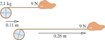
A string is wrapped around a disk of mass 2.1 kg (its density is not necessarily uniform). Starting from rest, you pull the
string with a constant force of 9 N along a nearly frictionless surface. At the instant when the center of the disk has moved
a distance 0.11 m, your hand has moved a distance of 0.28 m (Figure 9.48).
|
|
(a)
|
At this instant, what is the speed of the center of mass of the disk?
|
|
|
(b)
|
At this instant, how much rotational kinetic energy does the disk have relative to its center of mass?
|
|
|
(c)
|
At this instant, the angular speed of the disk is 7.5 radians/s. What is the moment of inertia of the disk?
|
|
|
|
|
|
|
| 9.P.34 |
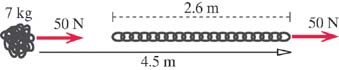
A chain of metal links with total mass M = 7 kg is coiled up in a tight ball on a low-friction table (Figure 9.49). You pull on a link at one end of the chain with a constant force F = 50 N. Eventually the chain straightens out to its full length L = 2.6 m, and you keep pulling until you have pulled your end of the chain a total distance d = 4.5 m.
|
|
(a)
|
Consider the point particle system. What is the speed of the chain at this instant?
|
|
|
(b)
|
Consider the real system. What is the change in energy of the chain?
|
|
|
(c)
|
In straightening out, the links of the chain bang against each other, and their temperature rises. Assume that the process
is so fast that there is insufficient time for significant transfer of energy from the chain to the table due to the temperature
difference, and ignore the small amount of energy radiated away as sound produced in the collisions among the links. Calculate
the increase in internal energy of the chain.
|
|
|
|
|
|
|
| 9.P.35 |
Tarzan, whose mass is 100 kg, is hanging at rest from a tree limb. Then he lets go and falls to the ground. Just before he
lets go, his center of mass is at a height 2.9 m above the ground and the bottom of his dangling feet are at a height 2.1
above the ground. When he first hits the ground he has dropped a distance 2.1, so his center of mass is (2.9 − 2.1) above
the ground. Then his knees bend and he ends up at rest in a crouched position with his center of mass a height 0.5 above the
ground.
|
|
(a)
|
Consider the point particle system. What is the speed v at the instant just before Tarzan's feet touch the ground?
|
|
|
(b)
|
Consider the real system. What is the net change in internal energy for Tarzan from just before his feet touch the ground
to when he is in the crouched position?
|
|
|
|
|
|
|
| 9.P.36 |
Here is an experiment on jumping up you can do.
|
|
(a)
|
Crouch down and jump straight up, as high as you can. Estimate the location of your center of mass, and measure its height
at three stages in this process: in the crouch, at lift-off, and at the top of the jump. Report your measurements. You may
need to have a friend help you make the measurements.
|
|
|
(b)
|
Analyze this process as fully as possible, using all the theoretical tools now available to you, especially the concepts in
this chapter. Include a calculation of the average force of the floor on your feet, the change in your internal energy, and
the approximate time of contact from the beginning of the jump to lift-off. Be sure to explain clearly what approximations
and simplifying assumptions you made in modeling the process.
|
|
|
|
|
|
|
| 9.P.37 |
In Section 9.1 we discussed a woman ice skater who pushes away from a wall.
|
|
(a)
|
Estimate the speed she can achieve just after pushing away from the wall. Then estimate the average acceleration during this
process. How many g's is this? (That is, what fraction or multiple of 9.8 m/s2 is your estimate?) Be sure to explain clearly what approximations and simplifying assumptions you made in modeling the process.
|
|
|
(b)
|
For this process, choose the woman as the system of interest and discuss the energy transfers, and the changes in the various
forms of energy. Estimate the amount of each of these, including the correct signs.
|
|
|
|
|
|
|
| 9.P.38 |
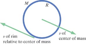
A hoop of mass M and radius R rolls without slipping down a hill, as shown in Figure 9.50. The lack of slipping means that when the center of mass of the hoop has speed v, the tangential speed of the hoop relative to the center of mass is also equal to vCM, since in that case the instantaneous speed is zero for the part of the hoop that is in contact with the ground ( v − v = 0). Therefore, the angular speed of the rotating hoop is ω = vCM/ R.
|
|
(a)
|
The initial speed of the hoop is vi, and the hill has a height h. What is the speed vf at the bottom of the hill?
|
|
|
(b)
|
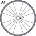
Replace the hoop with a bicycle wheel whose rim has mass M and whose hub has mass m, as shown in Figure 9.51. The spokes have negligible mass. What would the bicycle wheel's speed be at the bottom of the hill?
|
|
|
|
|
|
|
| 9.P.39 |
A sphere or cylinder of mass M, radius R, and moment of inertia I rolls without slipping down a hill of height h, starting from rest. As explained in Problem 9.P.38, if there is no slipping ω = vCM/ R.
|
|
(a)
|
In terms of the given variables (M, R, I, and h), what is vCM at the bottom of the hill?
|
|
|
(b)
|
If the object is a thin hollow cylinder, what is vCM at the bottom of the hill?
|
|
|
(c)
|
If the object is a uniform-density solid cylinder, what is vCM at the bottom of the hill?
|
|
|
(d)
|
If the object is a uniform-density sphere, what is vCM at the bottom of the hill?
|
|
An interesting experiment that you can perform is to roll various objects down an inclined board and see how much time each
one takes to reach the bottom.
|
|
|
|
|
| 9.P.40 |
Two disks are initially at rest, each of mass M, connected by a string between their centers, as shown in Figure 9.52. The disks slide on low-friction ice as the center of the string is pulled by a string with a constant force F through a distance d. The disks collide and stick together, having moved a distance b horizontally.
|
|
(a)
|
What is the final speed of the stuck-together disks?
|
|
|
(b)
|
When the disks collide and stick together, their temperature rises. Calculate the increase in internal energy of the disks,
assuming that the process is so fast that there is insufficient time for there to be much transfer of energy to the ice due
to a temperature difference. (Also ignore the small amount of energy radiated away as sound produced in the collisions between
the disks.)
|
|
|
|
|
|
|
| 9.P.41 |
You hang by your hands from a tree limb that is a height
L above the ground, with your center of mass a height h above the ground and your feet a height d above the ground, as shown in Figure 9.53. You then let yourself fall. You absorb the shock by bending your knees, ending up momentarily at rest in a crouched position
with your center of mass a height b above the ground. Your mass is M. You will need to draw labeled physics diagrams for the various stages in the process.
|
|
(a)
|
What is the net internal energy change ΔEint in your body (chemical plus thermal)?
|
|
|
(b)
|
What is your speed v at the instant when your feet first touch the ground?
|
|
|
(c)
|
What is the approximate average force F exerted by the ground on your feet during the time when your knees are bending?
|
|
|
(d)
|
How much work is done by this force F?
|
|
|
|
|
|
|
| 9.P.42 |
A box and its contents have a total mass M. A string passes through a hole in the box (Figure 9.54), and you pull on the string with a constant force F (this is in outer space—there are no other forces acting).
|
|
(a)
|
Initially the speed of the box was vi. After the box had moved a long distance w, your hand had moved an additional distance d (a total distance of w + d), because additional string of length d came out of the box. What is now the speed vf of the box?
|
|
|
(b)
|
If we could have looked inside the box, we would have seen that the string was wound around a hub that turns on an axle with
negligible friction, as shown in Figure 9.55. Three masses, each of mass m, are attached to the hub at a distance r from the axle. Initially the angular speed relative to the axle was ωi. In terms of the given quantities, what is the final angular speed relative to the axis, ωf?
|
|
|
|
|
|
|
| 9.P.43 |
Two identical 0.4 kg blocks (labeled 1 and 2) are initially at rest on a nearly frictionless surface, connected by an unstretched
spring, as shown in the upper portion of Figure 9.56. Then a constant force of 100 N to the right is applied to block 2, and at a later time the blocks are in the new positions
shown in the lower portion of Figure 9.56. At this final time, the system is moving to the right and also vibrating, and the spring is stretched.
|
|
Motion of the Center of Mass of the Real System
|
|
|
(a)
|
What is the initial location of the center of mass of the real system?
|
|
|
(b)
|
What is the final location of the center of mass of the real system?
|
|
|
(c)
|
How far did the center of mass of the real system move?
|
|
|
|
Point Particle System
|
|
| (d) |
What is the initial location of the point particle system?
|
|
| (e) |
What is the final location of the point particle system?
|
|
| (f) |
How far did the point particle system move?
|
|
| (g) |
In the point particle system, what was the distance through which the point of application of the force moved?
|
|
| (h) |
How much work was done on the point particle system?
|
|
| (i) |
List all the forms of energy that change in the point particle system during this process.
|
|
| (j) |
What was the change in the translational kinetic energy of the point particle system?
|
|
| (k) |
What is the final translational kinetic energy of the point particle system?
|
|
| (l) |
What is the mass of the point particle system?
|
|
| (m) |
What is the final speed of the point particle system?
|
|
|
|
Real System
|
|
| (n) |
The force was applied to a location on the right-hand edge of block 2. Look carefully at the diagrams. In the real system,
what was the distance through which the point of application of the force moved?
|
|
| (o) |
How much work was done on the real system?
|
|
| (p) |
List all the forms of energy that change in the real system during this process (assume that the vibrating spring doesn't
get hot).
|
|
| (q) |
What is the change in energy of the real system?
|
|
| (r) |
What is the final energy for the real system?
|
|
| (s) |
What is the final translational kinetic energy of the real system?
|
|
| (t) |
What is the final speed of the center of mass of the real system?
|
|
| (u) |
What is the final vibrational energy of the real system (spring potential energy plus kinetic energy relative to the center
of mass)?
|
|
| (v) |
The spring stiffness is 50 N/m. What is the final spring potential energy of the real system?
|
|
| (w) |
What is the final vibrational kinetic energy of the real system?
|
|
|
|
|
|
|
| 9.P.44 |
You hold up an object that consists of two blocks at rest, each of mass M = 5 kg, connected by a low-mass spring. Then you suddenly start applying a larger upward force of constant magnitude F = 167 N (which is greater than 2 Mg). Figure 9.57 shows the situation some time later, when the blocks have moved upward, and the spring stretch has increased.
The heights of the centers of the two blocks are as follows:
|
|
Initial and final positions of block 1: y1i = 0.3 m, y1f = 0.5 m
|
|
|
Initial and final positions of block 2: y2i = 0.7 m, y2f = 1.2 m
|
|
It helps to show these heights on a diagram. Note that the initial center of mass of the two blocks is ( y1i + y2i)/2, and the final center of mass of the two blocks is ( y1f + y2f)/2.
|
|
(a)
|
Consider the point particle system corresponding to the two blocks and the spring. Calculate the increase in the total translational
kinetic energy of the two blocks. It is important to draw a diagram showing all of the forces that are acting, and through
what distance each force acts.
|
|
|
(b)
|
Consider the real system corresponding to the two blocks and the spring. Calculate the increase of (Kvib + Us), the vibrational kinetic energy of the two blocks (their kinetic energy relative to the center of mass) plus the potential
energy of the spring. It is important to draw a diagram showing all of the forces that are acting, and through what distance
each force acts.
|
|
|
|
|
|
|
| 9.P.45 |
A box contains machinery that can rotate. The total mass of the box plus the machinery is 7 kg. A string wound around the
machinery comes out through a small hole in the top of the box. Initially the box sits on the ground, and the machinery inside
is not rotating (left side of Figure 9.58). Then you pull upward on the string with a force of constant magnitude 130 N. At an instant when you have pulled 0.6 m of
string out of the box (indicated on the right side of Figure 9.58), the box has risen a distance of 0.2 m and the machinery inside is rotating.
|
|
|
|
|
Point Particle System
|
|
|
(a)
|
List all the forms of energy that change for the point particle system during this process.
|
|
|
(b)
|
What is the y component of the displacement of the point particle system during this process?
|
|
|
(c)
|
What is the y component of the net force acting on the point particle system during this process?
|
|
|
(d)
|
What is the distance through which the net force acts on the point particle system?
|
|
|
(e)
|
How much work is done on the point particle system during this process?
|
|
|
(f)
|
What is the speed of the box at the instant shown in the right side of Figure 9.58?
|
|
|
(g)
|
Why is it not possible to find the rotational kinetic energy of the machinery inside the box by considering only the point
particle system?
|
|
|
|
Real System
|
|
| (h) |
The real system consists of the box, the machinery inside the box, and the string. List all the forms of energy that change
for the real system during this process.
|
|
| (i) |
What is the translational kinetic energy of the real system, at the instant shown in the right side of Figure 9.58?
|
|
| (j) |
What is the distance through which the gravitational force acts on the real system?
|
|
| (k) |
How much work is done on the system by the gravitational force?
|
|
| (l) |
What is the distance through which your hand moves?
|
|
| (m) |
How much work do you do on the real system?
|
|
| (n) |
At the instant shown in the right side of Figure 9.58, what is the total kinetic energy of the real system?
|
|
| (o) |
What is the rotational kinetic energy of the machinery inside the box?
|
|
|
|
|
|
|
|
|
Sections 9.6, 9.7 |
|
| 9.P.46 |
It is sometimes claimed that friction forces always slow an object down, but this is not true. If you place a box of mass
M on a moving horizontal conveyor belt, the friction force of the belt acting on the bottom of the box speeds up the box. At
first there is some slipping, until the speed of the box catches up to the speed v of the belt. The coefficient of friction between box and belt is μ.
|
|
(a)
|
What is the distance d (relative to the floor) that the box moves before reaching the final speed v? Use energy arguments, and explain your reasoning carefully.
|
|
|
(b)
|
How much time does it take for the box to reach its final speed?
|
|
|
(c)
|
The belt and box of course get hot. Is the effective distance through which the friction force acts on the box greater than
or less than d? Give as quantitative an argument as possible. You can assume that the process is quick enough that you can neglect transfer
of energy Q due to a temperature difference between the belt and the box. Do not attempt to use the results of the friction analysis in this chapter; rather, apply the methods of that analysis to this different situation.
|
|
|
(d)
|
Explain the result of part (c) qualitatively from a microscopic point of view, including physics diagrams.
|
|
|
|
|
|
|
|
|
| Copyright © 2011 John Wiley & Sons, Inc. All rights reserved. |


 is the location (relative to the origin) of the center of mass of the object whose total mass is M1, and so on.


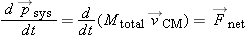
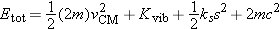
 is clearly unaffected by the translational motion of the center of mass, because it depends only on the stretch of the distance
between the two atoms.
is clearly unaffected by the translational motion of the center of mass, because it depends only on the stretch of the distance
between the two atoms.
 relative to the center of mass, and resolve its momentum into “tangential” and “radial” components (Figure 9.12). By “radial” component we mean a component in the direction of the line from the center of mass to the particle. By “tangential”
component we mean a component perpendicular to that line. If the particle is in circular motion around the center of mass,
the radial component is zero, so tangential momentum is associated with rotation. Radial momentum is associated with vibration.
relative to the center of mass, and resolve its momentum into “tangential” and “radial” components (Figure 9.12). By “radial” component we mean a component in the direction of the line from the center of mass to the particle. By “tangential”
component we mean a component perpendicular to that line. If the particle is in circular motion around the center of mass,
the radial component is zero, so tangential momentum is associated with rotation. Radial momentum is associated with vibration.
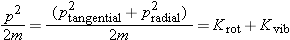


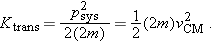


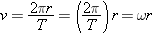
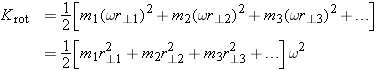
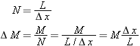
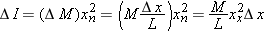
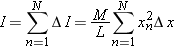
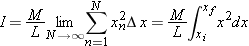
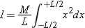
 . It doesn't matter how long the cylinder is (or to put it another way, how thick the disk is). See Figure 9.24.
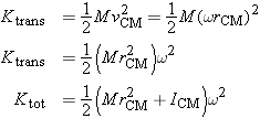
 . We can summarize this result by saying that the total kinetic energy is
  , where
 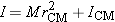 . This result is called the parallel axis theorem.
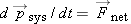 , the center of mass of a multiparticle system moves exactly like a simple “point” particle whose mass is the mass of the
entire system, under the influence of the net external force applied to the entire system. Pretend you could crush the real
system down to a very tiny ball and apply to this “point particle” forces with the same magnitudes and directions as those
that acted on the real system, but applied directly to the point particle rather than at their original locations. What would
the motion of this point particle system look like? It would look exactly like the motion of the center of mass of the real
system (Figure 9.27).
, the center of mass of a multiparticle system moves exactly like a simple “point” particle whose mass is the mass of the
entire system, under the influence of the net external force applied to the entire system. Pretend you could crush the real
system down to a very tiny ball and apply to this “point particle” forces with the same magnitudes and directions as those
that acted on the real system, but applied directly to the point particle rather than at their original locations. What would
the motion of this point particle system look like? It would look exactly like the motion of the center of mass of the real
system (Figure 9.27).

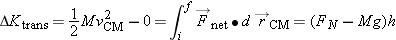

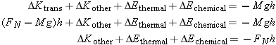
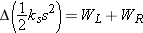
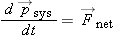


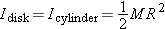

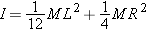
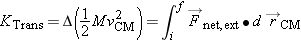
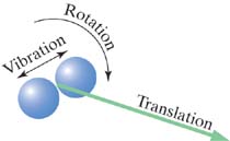
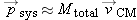 (if
(if 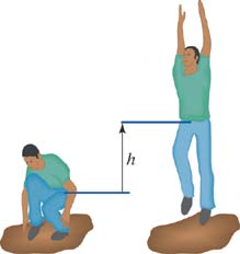
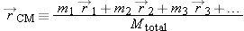
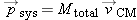
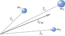
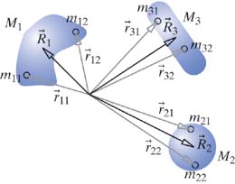
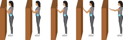
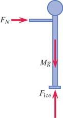
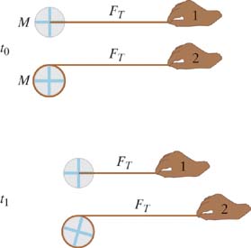

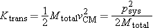
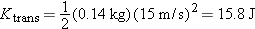


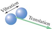
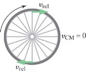
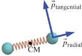
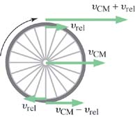
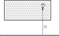
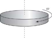
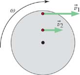

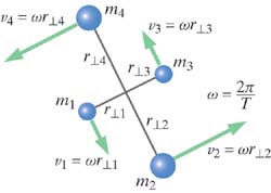
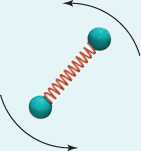
 . The distance between masses is
  . Therefore


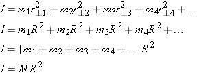
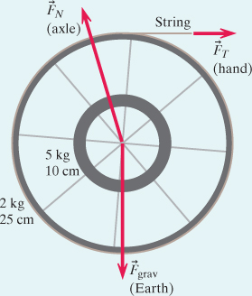
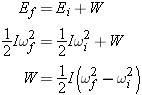
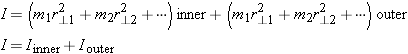
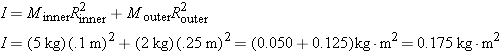

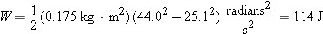
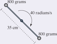
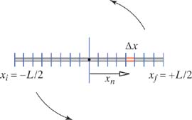


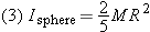
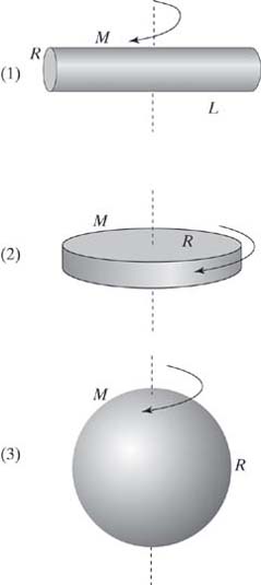
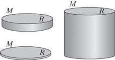
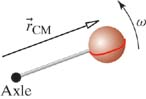
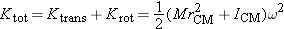
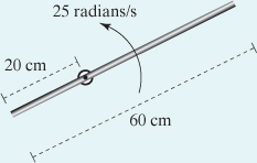
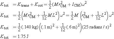


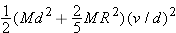
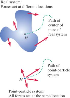


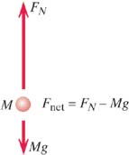
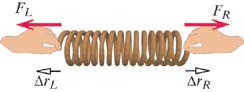
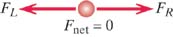
 ? How far does the center of mass move? How much work
  is done? What is the change in
 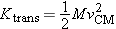 ?
?
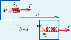
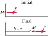

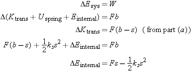
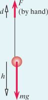
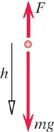
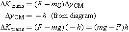


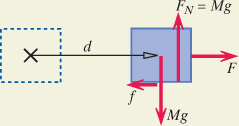


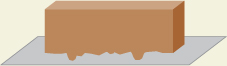
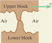
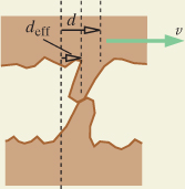
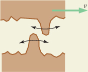
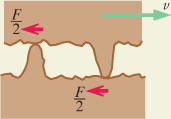
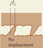

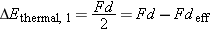
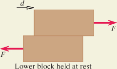
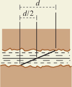
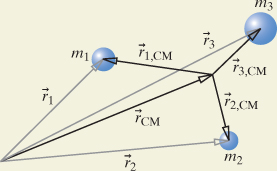
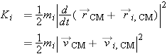

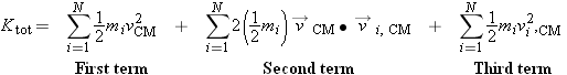
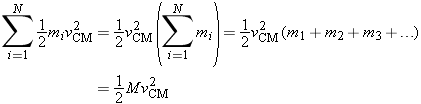

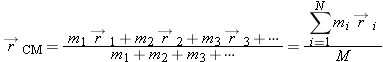
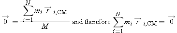
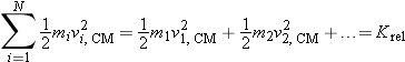
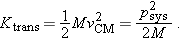
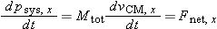
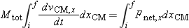
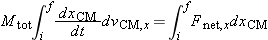
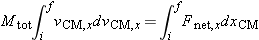
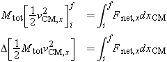
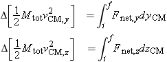


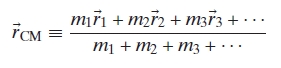
 ,
,  m/s
m/s
 ,
,  m/s
m/s
 ,
,  m/s
m/s