|
|
|
Electric Fields and Matter |
|
|
|
|
 |
|
 |
|
|
|
Charged Particles in Matter |
|
Since ordinary matter is composed of charged particles, electric fields can affect matter. In order to understand the effect
of electric fields on matter, in this chapter we will extend our microscopic model of matter to include the fact that matter
contains charged particles: protons and electrons.
Net Charge
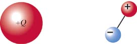
Elementary particles such as protons and electrons are electrically charged. If a proton and an electron combine to form a
hydrogen atom, however, the hydrogen atom is electrically “neutral”—its net charge is the sum of the charges of its constituent
particles, which in this case is zero:
A sodium atom has 11 protons in its nucleus and 11 electrons surrounding the nucleus, so it has a net charge of zero and is
electrically neutral. However, a sodium atom can lose an electron, becoming a sodium ion, Na
+.
A sodium ion has 11 protons and 10 electrons, so its net charge is
Ordinary matter is electrically neutral. However, it is possible to remove or add charged particles, giving an object a nonzero
net charge.
A dipole is neutral, because the sum of its constituent charges is zero:
Evidently even a neutral object can make a nonzero electric field in the surrounding space.
Conservation of Charge
In an extremely wide variety of experiments, no one has ever observed a change in the net charge of the universe. These results
are summarized by the fundamental principle called “conservation of charge”: if the net charge of a system changes, the net
charge of the surroundings must change by the opposite amount. For example, if your comb acquires negative charge, your hair
acquires an equal amount of positive charge:
Consider the annihilation reaction between an electron and a positron:
No. The net charge of the system (electron plus positron) was initially zero; the charge of the two photons is also zero.
Even though charged particles were destroyed, the net charge of the system did not change.
| 15.X.1 |
A carbon atom is composed of 6 protons, 6 neutrons, and 6 electrons. What is the net charge of this atom?
Answer:
0
|
|
|
|
|
| 15.X.2 |
A neutral chlorine atom contains 17 protons and 17 electrons. When a chlorine atom gains one extra electron, it becomes a
chloride ion. What is the net charge of a chloride ion?
Answer:
 C
|
|
|
|
|
|
|
|
|
Conductors and Insulators
All materials are made of atoms that contain electrons and protons. However, at the microscopic level there can be differences
in structure that lead to very different behavior when macroscopic objects are exposed to electric fields. In this chapter
we will examine two different kinds of materials: conductors and insulators. (There are other classes of technologically important
materials, such as semiconductors and superconductors, which we will discuss briefly in later chapters.)
Insulators
Many materials are made up of molecules that do not easily break apart, and whose electrons are tightly bound to the molecules
and can move only very short distances (typically less than the diameter of an atom). These materials are called insulators
because such materials can electrically “insulate” one charged object from another, since charged particles cannot flow through
the material. You are familiar with many insulating materials, such as rubber, most plastics, wood, paper, and glass.
Conductors
Other materials contain charged particles, such as ions or electrons, that are free to move through the material. These materials
are called conductors. Most metals, such as copper, silver, iron, aluminum, and gold, are excellent conductors; aqueous salt
solutions are also conductors. In the next section we will focus on interactions involving materials that are insulators;
we will discuss conductors, particularly metals, in a subsequent section.
|
 |
|
Definition of “Conductor” and “Insulator” |
|
 |
|
|
|
 |
|
 |
|
|
How Insulators become Charged |
|
Many of the interactions we observe in our everyday lives are electric in nature. By being systematic in observing the behavior
of simple systems, and by thinking carefully in our analysis of this behavior, we can uncover some deep questions about the
interaction of ordinary matter with electric fields.
In experimenting with charged objects such as invisible tape we find the following:
|
|
|
There are two kinds of charge, (which are called “+” and “−”).
|
|
|
|
|
|
|
|
The electric force
|
|
▪
|
acts along a line between the charges,
|
|
|
▪
|
decreases rapidly as the distance between the charges increases, and
|
|
|
▪
|
is proportional to the amounts of both charges.
|
|
|
|
Charging by Rubbing
A charged object that has a net negative charge has more electrons than protons. A positively charged object has fewer electrons
than protons.
There are a variety of possible explanations for this phenomenon. Electrons could be removed from one object and transferred
to the other object. Large organic molecules in the plastic or your hair may break at their weakest bond in such a way that
negative ions (negatively charged fragments) are deposited on the plastic and/or positive ions (positively charged fragments)
are deposited on your hair. It may be significant that almost the only materials that can be charged easily by rubbing are
those that contain large organic molecules, which can be broken fairly easily. It is typically more difficult to pull single
electrons out of atoms or molecules, although we cannot rule out the possibility of stripping a single electron out of a molecule.
Glass (silicon dioxide) is one of the few common inorganic materials that can be charged easily by rubbing, with silk. It
may be that positive ions break off the large organic molecules in the silk and are deposited on the glass, or that silk strips
single electrons off of glass.
Molecular breakage or electron transfer provides an explanation of our puzzle as to why tapes and combs get charged, but such
details as to why the plastic rather than your hair becomes negative are the subject of continuing research by physicists,
chemists, and materials scientists. Part of the complexity of these phenomena is due to the fact that they are surface phenomena.
The special nature of intermolecular interactions at the surface of a solid are generally less well understood than those
in the interior, and there is a great deal of current research on the properties of surfaces. Moreover, unless one takes extraordinary
precautions, real surfaces are always “dirty” with various kinds of (possibly charged) contaminants, which further complicates
any prediction about the effect of rubbing, which may remove or deposit charged contaminants.
It is known that rubbing is not essential to transferring charge from one object to another. Mere contact is sufficient. However,
rubbing produces many points of contact, which facilitates transfer.
Protons Are Not Removed from Nuclei
One thing is certain: you cannot remove bare nuclei from inside the surface atoms or remove protons from inside the nuclei
of the surface atoms by rubbing. The amount of energy required to do this would be enormous. Removing protons would amount
to transmuting one element into another! The nucleus is buried deep inside the atom, and the protons are bound tightly in
the nucleus. A much smaller force is required to remove one electron from an atom, or to break a chemical bond and transfer
an entire ion to another object. Therefore the only charged objects that can be transferred by rubbing are positive or negative
ions, or electrons.
We can make an approximate comparison of the energy required to charge an object by different mechanisms: breaking a bond,
removing an electron from an atom, or removing a proton from a nucleus. We saw in Chapter 8 (Energy Quantization) that the energy required to ionize a hydrogen atom (that is, to move the electron very far away from
the nucleus) was about 14 eV (recall that 1 eV = 1.6 × 10⁻¹⁹ J), so we can estimate the energy required to remove an electron from any atom as about 10 eV. The energy required to break
one of the oxygen–hydrogen bonds in water is about 450 kJ/mol, or about 4.6 eV per bond, so we can estimate the energy required
to break an average chemical bond as about 5 eV. As we saw in Chapter 6 (The Energy Principle), an input of about 2.2 MeV (2.2 × 10⁶ eV) is required to break apart the nucleus of a deuterium atom, which consists of one proton and one neutron, so we can estimate
the energy required to remove a proton from a nucleus as about 1 × 10⁶ eV.
|
|
|
Mechanism
|
Energy Required
|
|
Break chemical bond
|
≈ 5 eV
|
|
Remove electron
|
≈ 10 eV
|
|
Remove proton from nucleus
|
≈ 1 × 10⁶ eV
|
|
|
|
|
|
|
|
It is clear that either breaking bonds or removing single electrons is a possible mechanism for charging a macroscopic object
by rubbing, but removing protons from the atomic nuclei is not!
The Location of Charge Transfer
The principle of conservation of charge requires that the net charge of the system remain unchanged. Since the tapes started
out neutral, the lower tape must now be positively charged, and the absolute value of the charge of each tape must be the
same. For example, if the charge of the upper tape is −1nC, the charge of the lower tape must be +1nC (1 nC = 1 × 10
−9 C).
How Much Charge Is on a Charged Object?
Objects like invisible tapes, plastic pens, Ping-Pong balls, balloons, and glass rods can be electrically charged by rubbing
with an appropriate material, ripping apart, or other similar contact. It would be useful to know approximately how much excess
charge is on an ordinary small object like these when it is charged. Even knowing an approximate order of magnitude would
be useful—is it closer to 10 coulombs, 0.1 coulomb, or 1 × 10⁻¹⁰ coulombs?
|
|
|
|
|
|
|
Momentum Principle:
In Figure 15.8, estimate the electric field due to A by approximating A as a point charge (a very rough approximation):
so
If the 20-cm-long piece of tape has a mass of about 0.15g, and the bottom tape starts to be lifted when the top tape is about
2.5 cm away, then since the magnitude of the charge on the tapes is the same,
|
|
|
|
|
|
|
Further Discussion
This is a rough estimate, but it turns out to be a reasonable one—a small object charged by rubbing usually has a charge on
the order of 10 nCs. In Chapter 16 we'll see how to calculate the electric field of an object that is not pointlike but has charge spread over its entire surface.
Using these techniques, we find that the electric field at a location very close to the surface of the charged tape is around
2 × 10⁵ N/C. Since the electric field required to ionize the air itself is about 3 × 10⁶ NC, the field near the surface of the charged tape is pretty large.
Fraction of Surface Atoms with Excess Charge
Assuming that the net charge on the negative tape is distributed uniformly over its surface, we can estimate the fraction
of those surface atoms that have gained an excess electron or negative ion.
|
|
|
|
|
|
|
Surface area of a 1-cm-wide, 20-cm-long tape:
Approximate cross-sectional area occupied by an atom whose radius is approximately 1 × 10 −10 m:
Number of atoms on the surface:
Number of excess electrons (or ions):
Fraction of surface atoms with excess charge:
Thus only about one in a million atoms on the surface of the tape has acquired an excess electron or lost an electron—a small
fraction.
|
|
|
|
|
|
Further Discussion
At the macroscopic level, the charge on the surface of the tape may appear to be distributed quite uniformly. At the atomic
level, though, we see that the atoms with excess charge are sprinkled quite sparsely over the surface.
|
Polarization |
|
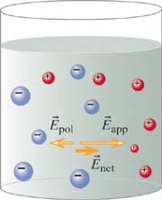
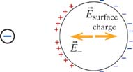
The attraction of both positively and negatively charged invisible tape to your hand, and to many other neutral objects, is
deeply mysterious. The net charge of a neutral object is zero, so your neutral hand should not make an electric field that
could act on a charged tape; nor should your neutral hand experience a force due to the electric field made by a charged tape.
Nothing in our statement of the properties of electric interactions allows us to explain this attraction!
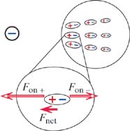
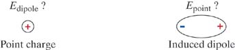
The Structure of an Atom
An external charge can cause a shift in the position of the charges that make up a neutral atom or molecule. To see this clearly
we need to look in more detail at the structure of atoms. We'll consider a hydrogen atom because it is the simplest atom,
but the effects we discuss occur with other atoms as well.
Figure 15.10 shows this probability graphically. You can think of the picture as a multiple exposure. For each exposure, the position
of the electron at that time is shown as a dot. Because the electron is most likely to be found near the nucleus, that part
of the multiple exposure is so dark you can't see the individual dots. The electron is seldom found a long way from the nucleus,
so as you get farther and farther from the nucleus the density of dots gets less and less.
We call this probability distribution the “electron cloud.” In hydrogen the cloud consists of just one electron, but in other
atoms the electron cloud is made up of many electrons. The average location of the electron is in the center, at the same
location as the nucleus. You're just as likely to find the electron to the right of the nucleus as to the left of the nucleus.
It is impossible to show the nucleus accurately on this scale. Although the mass of a proton is 2000 times the mass of an
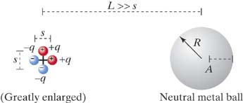
electron, the radius of the proton, about 1 × 10⁻¹⁵ cm, is only about 1/100,000 as big as the radius of the electron cloud, which is itself only about 1 × 10⁻¹⁰ meters! We used an oversize red dot to mark the position of the tiny nucleus in Figure 15.10.
In the following exercise, remember that in the previous chapter we pointed out that the electric field produced by a uniformly
distributed sphere of charge, outside the sphere, is the same as though all the charge were located at the center of the sphere
(this will be discussed in more detail in Chapter 16).
| 15.X.3 |
A student asked, “Since the positive nucleus of the atom is hidden inside a negative electron cloud, why doesn't all matter
appear to be negatively charged?” Explain to the student the flaw in this reasoning.
Answer:
The student has forgotten to consider the superposition principle. Electric interactions go right through matter, so the effect
of the positive nucleus is not blocked by the surrounding electron cloud. There are exactly as many protons in the nucleus
as there are electrons, and normally the electron cloud is centered on the nucleus, so the net effect is zero.
|
|
|
|
|
|
|
|
|
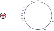
Polarization of Atoms
If the electron cloud in an atom could be considered to be spherically uniform and always centered on the nucleus, a neutral
atom would have no interaction with an external charge. If the electron cloud is centered on the nucleus, the electric field
produced by the N electrons would exactly cancel the field produced by the N protons. However, the electron cloud doesn't always stay centered, as we'll see next.
In an atom the electron cloud is not rigidly connected to the nucleus. The electron cloud and the nucleus can move relative
to each other. If an external charge is nearby, it creates an electric field, which exerts forces on the electron cloud and
on the nucleus. Under the influence of this “applied” electric field the electron cloud and the nucleus shift position relative
to each other.
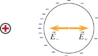
Average Location of the Electron
The average location of the electron is now not at the center where the nucleus is located, but is displaced somewhat to the
left of the nucleus. That is, each time you take a snapshot, you're more likely to find the electron to the left of the nucleus
than to the right of the nucleus.
The hydrogen atom isn't immediately torn apart, because the attraction between the nucleus and the electron is stronger than
the forces exerted by the distant external charge. However, if the external charge gets very close the hydrogen atom may break up or react with the external charge. If the external charge were a proton, it could combine
with the hydrogen atom to form ionized molecular hydrogen (H2+).
You can see in Figure 15.11 that the outer regions of the cloud are affected the most by the external charge. This is because in the outer regions the
electron is farther from the nucleus and can be influenced more by the external positive charge. In an atom containing several
electrons, the outer electrons are affected the most. The picture is deliberately exaggerated to show the effect: unless the
polarization is caused by charges only a few atomic diameters away, the shift in the electron cloud is normally too small
to represent accurately in a drawing.
An atom is said to be “polarized” when its electron cloud has been shifted by the influence of an external charge so that
the electron cloud is not centered on the nucleus.
Diagrams of Polarized Atoms or Molecules
Induced Dipoles Are Created by Applied Electric Fields
Figure 15.12 shows quite clearly that a polarized atom or molecule is a dipole, since there are two opposite charges separated by a distance.
However, the polarized atom or molecule is not a permanent dipole. If the applied electric field is removed (for example,
by removing the charges making that field), the electron cloud will shift back to its original position, and there will no
longer be any charge separation. We call the polarized atom or molecule an “induced” dipole, because the dipole was induced
(caused) to form by the presence of an applied electric field.
An “induced dipole” is created when a neutral object is polarized by an applied electric field. The induced dipole will vanish
if the applied field is removed.
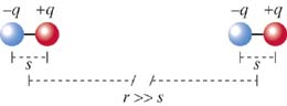
A “permanent dipole” consists of two opposite charges separated by a fixed distance, such as HCl or H2O molecules, or the dipole that can be constructed out of + and − tapes (Experiment 15.EXP.20).
Polarizability
It has been found experimentally that for almost all materials, the amount of polarization induced (that is, the dipole moment

of the polarized atoms or molecules) is directly proportional to the magnitude of the applied electric field. This result
can be written like this:
|
|
 The magnitude of the electric dipole moment of a dipole is:
and the direction is from the negative charge toward the positive charge (see Chapter 14).
|
|
|
The constant
a is called the “polarizability” of a particular material. The polarizability of many materials has been measured experimentally,
and these experimental values may be found in reference volumes.
| 15.X.4 |
In an induced dipole, is the distance between the charges fixed, or can it vary? Explain.
Answer:
It varies and is proportional to strength of applied field.
|
|
|
|
|
| 15.X.5 |
A typical atomic polarizability is 1 × 10−40 C · m/(N/C). If the q in p = qs is equal to the proton charge e, what charge separation s could you produce in a typical atom by applying a large field of 3 × 10⁶ N/C, which is large enough to cause a spark in air?
Answer:
2 × 10⁻¹⁵, about the diameter of a proton!
|
|
|
|
|
|
|
|
|
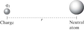
A Neutral Atom and a Point Charge
In the previous chapter we found that since the electric field of a dipole was proportional to 1/r3, the force exerted by a dipole on a point charge was also proportional to 1/r3. Because of the reciprocity of the electric force, the force on the dipole by the point charge was therefore also proportional
to 1/r3. Let us extend this analysis by considering the case of a point charge q1 and a neutral atom.
Even though the entire process happens very quickly, it is instructive to analyze it as if it occurred in several steps. (Of
course, the process is not instantaneous, since information about changes in electric field takes a finite time to propagate
to distant locations.)
The atom is now polarized, with dipole moment

proportional to the applied electric field

.
Since we know
, the electric field of the point charge at the location of the dipole, we can put that into our equation:
We find that the force on the point charge by the polarized atom is proportional to 1/
r5.
Because of the reciprocity of the electric interaction (Newton's third law), the force on the neutral atom by the point charge
is equal in magnitude and opposite in direction to the force on the point charge by the neutral atom:
so the force on a (polarized) neutral atom by a point charge also is proportional to 1/
r5.
| 15.X.6 |
Atom A is easier to polarize than atom B. Which atom, A or B, would experience a greater attraction to a point charge a distance r away?
Answer:
A: If an atom is more easily polarizable, the separation of charge in the atom will be greater. The larger the dipole moment,
the larger is the force.
|
|
|
|
|
| 15.X.7 |
If the distance between a neutral atom and a point charge is doubled, by what factor does the force on the atom by the point
charge change?
Answer:
2−5 = 1/32
|
|
|
|
|
|
|
|
|
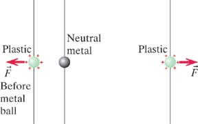
Interaction of Charged Objects and Neutral Matter
We are now in a position to explain why both positively and negatively charged objects (such as + and − tapes) are strongly
attracted to neutral matter.
In considering the interactions of fields and matter, the following scheme is useful. (1) Identify any sources of electric
fields. (2) Identify any charges at other locations that can be affected by these fields. (3) Redistribution of the affected
charges may create an electric field at the location of the original source charges: are they affected?
You may have noticed that the attraction between your neutral hand and a hanging charged invisible tape changes much more
rapidly with distance (1/r5) than does the interaction between two charged tapes (1/r2).
| 15.X.8 |
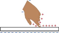
Explain in detail, including diagrams, what happens when a negatively charged tape is brought near your finger.
Answer:
Negative tape is attracted to finger:
|
|
|
|
|
|
|
|
|
Determining the Charge of an Object
Suppose that you have a negatively charged tape hanging from the desk, and you rub a wooden pencil on a wool sweater and bring
it near the tape.
Not necessarily. Even if the pencil is uncharged, the charged tape will polarize the pencil and be attracted by the induced
dipoles.
Polarization always brings the unlike-sign charge closer, yielding a net attraction. Repulsion of an induced dipole can't
happen. Therefore repulsion is the better test of whether an object is charged.
Electric Field Penetrates Intervening Matter
The superposition principle states that the presence of matter does not affect the electric field produced by a charged object.
Intervening matter does not “screen” or “shield” the electric field, just as your desk does not “screen” or “shield” your
book from the gravitational field of the Earth.
You may have already observed one case of electric field passing through intervening matter. You see the same interaction
between a charged invisible tape and your hand, or another tape, when approaching either side of a hanging tape, despite the
charges being on just one side of the tape. The charges are initially on either the slick side or the sticky side (depending
on whether it is the upper or lower tape in a pair of tapes), and one can show that the charges can't move through the tape
to the other side (Experiment 15.EXP.23).
Intervening Matter and Superposition
The fact that an electric field acts through intervening matter is another example of the superposition principle. It is true
that the repulsion between two like-charged pieces of tape is weaker when a piece of paper is in the way (Experiment 15.EXP.22), but when viewed in terms of the superposition principle this reduction is not due to the paper partially “blocking” the
field of the other tape. Rather, we say that the net field is due to the superposition of two fields: the same field that you would have had without the paper intervening, plus another field due to the induced dipoles in the paper.
|
Polarization of Insulators |
|
In insulators, all of the electrons are firmly bound to the atoms or molecules making up the material. We have seen that an
individual atom or molecule can be polarized by an applied electric field, producing an induced dipole of atomic or molecular
dimensions. The electrons in an atom or molecule of an insulator shift position slightly, but remain bound to the molecule—no
charged particles can move more than about one atomic diameter, or 1 × 10⁻¹⁰ m (most move much less than this distance; see Exercise 15.X.5).
Polarization Happens Very Rapidly
Because the electron cloud is displaced only a tiny distance when an atom or molecule polarizes, this process happens extremely
rapidly. The process can take much less than a nanosecond to complete.
Diagrams Showing Polarization of Insulators
In diagrams of insulators we show polarized molecules exaggerated in size, to indicate that individual molecules in an insulator
polarize, but the electrons remain bound to the molecule. We show the extent of polarization by the degree to which the molecule
is “stretched.” Keep this diagrammatic convention in mind, and compare it to diagrams of polarized conductors in the following
sections.
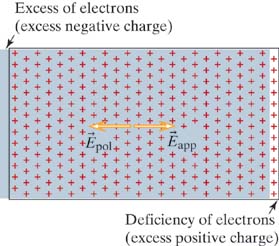
Charge on or in an Insulator
Low-Density Approximation
When atoms or molecules in an insulator polarize in response to an electric field created by external charged objects, the
polarized molecules themselves make electric fields that affect neighboring molecules. Because the effect of polarized molecules
on each other is typically small compared to the effect of the original applied field, we will neglect this when discussing
polarized insulators.
In formal terms, when an electric field
Eapplied is applied to a dense material (a solid or a liquid), the induced dipole moment of one of the atoms or molecules in the material
isn't simply
p = α
Eapplied, but is really
, where
Edipoles is the additional electric field at the location of one of the molecules, due to all the other induced dipoles in the material.
In this text we make the simplifying assumption of low density and assume that
Edipoles is small compared to
Eapplied. This is good enough for our purposes, but accurate measurements of polarizability must take this effect into account.
|
Polarization of Conductors |
|
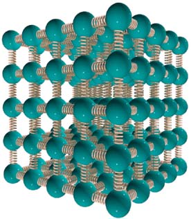
As we stated earlier, a conductor has some kind of charged particles that can move freely throughout the material. In contrast
to an insulator, where electrons and nuclei can move only very small distances (around 1 × 10⁻¹⁰ m, or much less), the charged particles in a conductor are free to move large distances.
Ionic Solutions
Ionic solutions are conductors, such as a solution of sodium chloride (table salt) in water. In salt water, the mobile charged
particles are Na
+ ions and Cl
− ions (Figure 15.21; there are also very small concentrations of H
+ and OH
− ions, which are not shown).
|
|
|
|
|
| Figure 15.21 |
A beaker containing an ionic solution (salt water).
|
|
|
|
|
Drift Speed and Applied Electric Field
If a beaker of salt water is placed in a region where there is an electric field (due to charges outside the beaker), a sodium
ion or a chloride ion will experience an electric force, and will begin to move in the direction of the force. However, even
if the force remains constant, the ion will not keep accelerating, because it will collide with water molecules or with other
ions. In effect, there is a kind of friction at the microscopic level.
To keep the ions in a salt solution moving at a constant speed, a constant electric field must be applied to the solution.
The speed at which mobile charges (in this case, sodium or chloride ions) move through a conductor is called the
drift speed. Drift speed is directly proportional to the net electric field at the location of the charge. The proportionality constant
is called the
mobility of the mobile charges.
As implied by this equation, if the net electric field at the location of a mobile charge in a conductor is zero, the charge
will stop moving.
| 15.X.9 |
An electric field of magnitude 190 N/C is applied to a solution containing chloride ions. The mobility of chloride ions in
solution is 7.91 × 10⁻⁸ (m/s)/(N/C). What is the average drift speed of the chloride ions in the solution?
Answer:
1.5 × 10⁻⁵ m/s
|
|
|
|
|
|
|
|
|
The Polarization Process in an Ionic Solution
Polarization occurs very rapidly, but it is not instantaneous. Let's “slow down time” so we can talk about the process of
polarization; we'll operate on a time scale of attoseconds (1 × 10⁻¹⁸ seconds!). To simplify our analysis, we'll imagine that we are able temporarily to “freeze” the ions in the salt water, and
to release them after we have brought charges nearby to apply an electric field.
At this instant the net electric field in the solution still has magnitude greater than zero, so ions in the solution will
still experience forces in the direction to increase the polarization. Because

, the drift speed

of the ions is not zero. More ions will pile up at the sides of the beaker, and the net electric field in the interior will
be further weakened.
An Example of a “Proof by Contradiction”
You may have correctly deduced that in the final state the net electric field in the conductor goes to zero at equilibrium.
A rigorous way to reason about this using formal logic is to construct a “proof by contradiction.” In a proof by contradiction,
we assume the opposite of what we want to prove, then, making valid logical deductions from this assumption, show that we
reach a conclusion that is impossible or contradictory. We therefore conclude that the original assumption was wrong, and
its opposite must be true.
|
|
1.
|
Assume that in equilibrium the net electric field in the interior of an ionic solution is greater than zero.
|
|
|
2.
|
Since Enet >, all mobile ions in the solution will experience a nonzero force. Since u > 0, the average drift speed  , and all ions move in the direction of the force.
|
|
|
3.
|
Since , there is a net flow of charges. Therefore the system cannot be in equilibrium, because by definition in equilibrium  and there is no net flow of charges. This result, that , contradicts our original assumption (point 1 above) that the ionic solution is in equilibrium.
|
|
|
4.
|
Because we have reached a contradiction, we must conclude that the original assumption (that the net electric field in the
solution may be nonzero in equilibrium) is wrong. Thus, we conclude that the net electric field in an ionic solution in equilibrium
must be zero.
|
|
This reasoning holds true for any conductor, including not only ionic solutions, but solid metal objects as well.
Superposition
Note that the electric field inside the liquid is zero, not because of any “blocking” of fields due to external charges, but
by the superposition of two effects: the effect of the external charges and the effect of the polarization charges. This is
another example of the superposition principle in action.
It is not true that the net electric field in a solution is zero at all times. While the ionic solution is in the process of polarizing, it is not in equilibrium; there is a nonzero electric field,
and hence a nonzero force on an ion in the liquid, as you saw above. If electrodes are placed in the ionic solution and connected
to a battery, the battery prevents the system from reaching equilibrium. In such a case (no equilibrium), there can be a field
continuously acting on ions inside the liquid, resulting in continuous shifting of the ions through the liquid, constituting
an electric current.
Since there are a very large number of ions in the solution, none of them has to move very far during the polarization process.
Even a tiny shift leads to the buildup of an electric field large enough to cancel out the applied electric field.
Polarization of Salt Water in the Body
Your own body consists mainly of salt water, including the blood and the insides of cells. Look again at the diagrams in which
you focused on the way an external charge polarizes individual molecules inside your finger. An additional effect is the polarization
of the salt water inside your finger. As shown in Figure 15.22, there will be a shift of Na+ and Cl− ions in the blood and tissues. This shift may be a larger effect than the molecular polarization. It is a bit unsettling
to realize that a charged tape or comb messes with the inside of your body!
|
A Model of a Metal |
|
You probably know that metals are very good electrical conductors. In almost all metals, the mobile charged particles are
electrons.
The Mobile Electron Sea
No Net Interaction between Mobile Electrons
Although the roaming electrons repel each other strongly, this repulsion between electrons is neutralized on the average by
the attractions exerted by the positive atomic cores (a “core” is a neutral atom minus its roaming electron, so it has a charge
of +e). The effect is that on average, the net electric field inside a piece of metal in equilibrium is zero.
Because of this, in some ways the mobile electrons look like an ideal gas: they move in a region free from the electric field,
so they appear not to interact with each other or with the atomic cores. In fact, in some simple models of electron motion
the mobile electron sea is treated as an ideal gas.
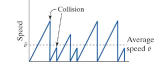
The Drude Model
Drift Speed and Electron Mobility
The average speed of an electron in this start–stop motion is called the “drift” speed
, and we say that the electron “drifts” through the metal. Actually, the slow drift motion is superimposed on high-speed motion
of the electrons in all directions inside the metal, much as the wind is a slow drift motion superimposed on the high-speed
motion of air molecules in all directions. A full treatment of electrons in a metal, including the reason for the high-speed
motion in all directions, requires quantum mechanics, but the simple classical Drude model allows us to understand most of
the important aspects of circuits on a microscopic level.
We express the momentum principle
in a form involving finite time steps for momentum in the direction of

,
where
Enet is the magnitude of the net electric field inside the wire, and Δ
t is the time between collisions. If we make the simplifying assumption that the electron loses all its momentum during each
collision, we have
The speed of the electron (of mass
me) at the time of collision turns out to be small compared to the speed of light, so we have
However, the time between collisions is not the same for all electrons. Some experience longer times between collisions, some
shorter times. To get an average, “drift” speed
for all electrons at a particular instant, we need the average time

between collisions:
, the average time between collisions of the electrons with the atomic cores, is determined by the high-speed random motion
of the electrons and by the temperature of the metal. (At a higher temperature the thermal motion of the atomic cores is greater,
and the average time between collisions is reduced, leading to a smaller drift speed for the same field
E.)
Assuming that increasing the electric field does not result in a significant change in temperature, then doubling the electric
field
E doubles the drift speed
attained in that time; hence the drift speed is directly proportional to the electric field. The proportionality factor is
called the electron “mobility” and is denoted by
u (or by μ in some books).
Evidently,
Different metals have different electron mobilities. The higher the mobility, the higher the drift speed for a given electric
field. The direction of the drift velocity of a mobile (negatively charged) electron is opposite to the direction of the electric
field.
| 15.X.10 |
The mobility of the mobile electrons in copper is 4.5 × 10⁻³ (m/s)/(N/C). How large an electric field would be required to give the mobile electrons in a block of copper a drift speed
of 1 × 10⁻³ m/s?
Answer:
0.22 N/C
|
|
|
|
|
|
|
|
|
Polarization Happens Very Quickly
The shift in the electron sea is extremely small, much less than an atomic diameter! (See Exercise 15.X.5.) It is not necessary for electrons at one end of the block to move to the other end. Just displace the entire electron sea
slightly and you have lots of excess electrons on one surface. Because the electron sea has to move only a tiny distance,
this displacement can happen very rapidly—it can take much less than a nanosecond.
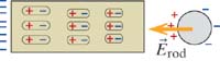
Diagrams Showing Polarization of Metals
Note that most charge buildup is typically on the ends of the metal, but that there is also a small amount of charge on the
sides as well.
Compare these conventions to the convention we used earlier to show the individual atoms or molecules polarize in an insulator.
Polarized and/or Charged
Take care to use technical terms precisely. The metal block shown in Figure 15.28 is polarized. It is not charged; its net charge is still zero.
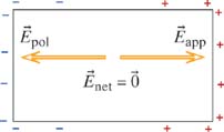
Net Electric Field in a Metal Goes to Zero in Equilibrium
The reasoning process that we went through when considering the polarization of ionic solutions applies equally well to metals,
or to any conductor. We used proof by contradiction to demonstrate that in equilibrium the net electric field inside a conductor
must be zero (because if it were not zero, mobile charged particles would move under the influence of the field, and the system
would not be in equilibrium).
It is intriguing that it is possible for mobile charges to rearrange themselves in such a way that the net electric field
is zero not just at one single location, but also at every location inside the metal. It would be a very difficult problem
for us to calculate exactly where to place charged particles to make a net field of zero inside a metal object, but in fact
the many mobile charges do rearrange in just such a way as to accomplish this. It can be shown that it is because of the 1/r2 distance dependence of the electric field that this is possible—if the exponent were not exactly 2.0, the world would be
quite different.
When equilibrium is reached in a metal, things are essentially unchanged in the interior of the metal. There is no excess
charge—we still have a uniform sea of electrons filling the space around the positive atomic core. The net electric field
inside the metal, which is the sum of the applied field and the field due to the charge buildup on the edges of the metal,
is still zero.
At the surfaces there is some excess charge, so we can represent a polarized metal as having thin layers of charge on its
surfaces but being unpolarized in the interior, unlike an insulator.
The shifting of the mobile electron sea in metals is a much larger effect than occurs in insulators, where the polarization
is limited by the fact that all the electrons, including the outermost ones, are bound to the atoms, unlike the situation
in metals. A polarized insulator is a collection of tiny (molecule-sized) dipoles, whereas a polarized metal forms one giant
dipole.
E is Not Always Zero inside a Metal
Do not overgeneralize our previous conclusions. It is not true that the net electric field in a metal is zero at all times.
While the metal is in the process of polarizing, the metal is not in equilibrium, and there is a nonzero electric field inside
the metal, creating a nonzero force on electrons in the electron sea, as you saw above. In an electric circuit, the battery
prevents the system from reaching equilibrium. In such a nonequilibrium situation, there can be an electric field inside the
metal, and hence a force continuously acting on electrons in the mobile electron sea, resulting in continuous shifting of
the electron sea around the closed circuit, constituting an electric current.
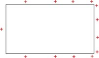
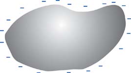
Excess Charges on Conductors
Here is a summary of the behavior of conductors vs. insulators:
|
|
| |
Conductor
|
Insulator
|
|
Mobile charges
|
Yes
|
No
|
|
Polarization
|
Entire sea of mobile charges moves
|
Individual atoms or molecules polarize
|
|
Equilibrium
|
 inside
|
 nonzero inside
|
|
Location of excess charge
|
Only on surface
|
Anywhere on or inside material
|
|
Distribution of excess charge
|
Spread out over entire surface
|
Located in patches
|
|
|
|
|
|
|
|
|
|
|
|
|
|
|
|
|
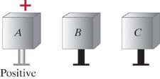
|
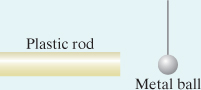
(a)
|
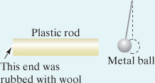
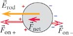
The plastic rod is an insulator, so the excess charge remains on the left-end surface of the rod.
This charge polarizes the molecules inside the rod.The original charge plus the polarized molecules make a field that polarizes
the neutral metal ball, as shown in Figure 15.34.
The field due to the plastic rod (charge on end plus polarized molecules) exerts a net force to the left on the polarized
metal ball (Figure 15.35).
|
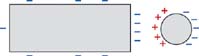
The excess charge on the polarized metal ball is on the surface of the ball, because the ball is a conductor. The interior
of the ball is neutral.
|
|
|
|
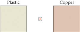
Both objects are conductors, so all excess charge is on the surfaces.
|
|
|
|
|
|
(b)
|
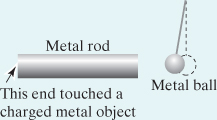
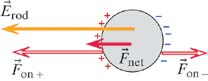
The excess negative charge spreads all over the surface of the metal rod, which is a conductor.
This excess negative charge polarizes the metal ball. The polarized metal ball in turn polarizes the negatively charged metal
rod somewhat, as shown in Figure 15.36.
Polarization of the ball is greater in this case, because more of the original charge is closer to the ball (Figure 15.37). The net force on the ball is greater in this case than it was with the plastic rod.
|
|
|
|
|
|
|
|
|
|
|
|
|
|
|
|
|
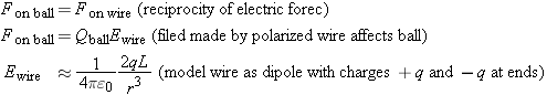
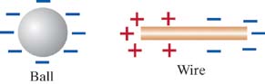
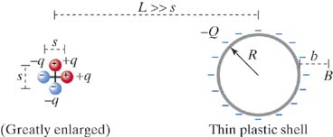
A Ball and a Wire
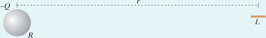
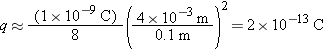
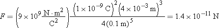
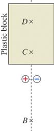
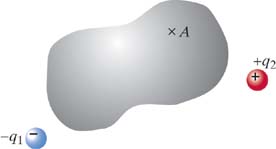
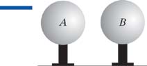
The center of a small spherical metal ball of radius R, carrying a negative charge − Q, is located a distance r from the center of a short, thin, neutral copper wire of length L (Figure 15.38). The ball and the wire are held in position by threads that are not shown. If R = 5 mm, Q = 1 × 10 −9 C, r = 10 cm, and L = 4 mm, calculate the force that the ball exerts on the wire.
|
|
|
|
|
|
|
|
|
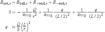
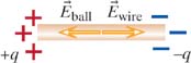
We need to find the charge q on one end of the wire. We know that at any location inside the metal wire, in equilibrium (Figure 15.40). Consider a location in the center of the wire, and model the wire as though there were + q and − q on the ends, a distance L apart, ignoring the small amount of charge on the rest of the wire (here we can't use dipole formulas; we're between the
charges).
|
|
|
|
|
| Figure 15.40 |
The net electric field inside the wire must be zero in equilibrium.
|
|
|
|
|
At a location outside the wire we model the wire as a dipole, so the force on the ball (which is equal in magnitude to the
force on the wire) is this:
Not too surprisingly, we find a force proportional to 1/ r5.
Now we can calculate numerical values:
which is a very small charge. This justifies our assumption that the polarized wire won't polarize the ball to any significant
extent. The force is tiny:
If we double r, there is 1/4 as much q and 1/32 as much force. If we double Q, there is 2 times as much q and 4 times as much force.
|
|
|
|
|
|
|
|
| 15.X.11 |
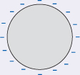
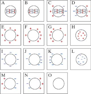
An object can be both charged and polarized. On a negatively charged metal ball, the charge is spread uniformly all over the surface (Figure 15.41). If a positive charge is brought near, the charged ball will polarize.
|
|
|
|
|
| Figure 15.41 |
This is a cross section of the metal ball.
|
|
|
|
|
|
|
(a)
|
Draw the approximate final charge distribution on the ball.
|
|
|
(b)
|
At the center, draw the electric field due to the external positive charge.
|
|
|
(c)
|
At the center, draw the electric field due to the charge on the surface of the ball.
|
|
|
(d)
|
At the center, draw the net electric field.
|
|
If any of these quantities is zero, state this explicitly.
Answer:
( a–d) Note shift of charge distribution; it is no longer uniform:
|
|
|
|
|
| 15.X.12 |
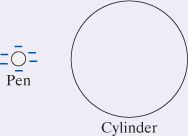
A negatively charged plastic pen is brought near a neutral solid metal cylinder (Figure 15.42).
|
|
|
|
|
| Figure 15.42 |
This is a cross section of the metal or plastic cylinder.
|
|
|
|
|
|
|
(a)
|
Show the approximate charge distribution for the metal cylinder.
|
|
|
(b)
|
Draw a vector representing the net force exerted by the pen on the metal cylinder, and explain your force vector briefly but
completely, including all relevant interactions.
|
|
|
(c)
|
At the center, draw the electric field due to the external negative charge.
|
|
|
(d)
|
At the center, draw the electric field due to the charge on the surface of the ball.
|
|
|
(e)
|
At the center, draw the net electric field.
|
|
|
(f)
|
Replace the solid metal cylinder with a solid plastic cylinder. Show the approximate charge distribution for the plastic cylinder
and draw a vector representing the net force exerted by the pen on the plastic cylinder; explain your force vector briefly
but completely, including all relevant interactions.
|
|
If any of these quantities is zero, state this explicitly.
Answer:
( a–f) Negative pen polarizes the neutral metal cylinder by shifting the electron sea; + charges are closer than − charges, so
the pen exerts a net attraction on the cylinder.
Negative pen polarizes the neutral plastic cylinder by polarizing the molecules; + charges are closer than − charges, so the
pen exerts a net attraction on the cylinder.
|
|
|
|
|
|
|
|
|
|
Charging and Discharging |
|
We have seen that objects made of insulators can often acquire a nonzero net charge if they are rubbed by another insulator.
You can charge initially neutral pieces of invisible tape by stripping them off other pieces of tape. You can charge an initially
neutral pen by rubbing it on your hair. In both these cases, some kind of charged particle is added to or removed from a surface
that was originally neutral. In Section 15.2 we discussed possible mechanisms for the transfer of charge between one insulating object and another, including the transfer
of positive or negative ions and the transfer of electrons.
Since a conducting object contains mobile charged particles, the process of charging or discharging a conductor involves a
flow of charged particles from one conductor to another. For example, electrons from the mobile electron sea in a metal object
can move into the mobile electron sea of a different metal object if the objects come into contact with each other.
Although you may not have previously thought of yourself as a conductor, your own body plays an interesting role in some kinds
of charging or discharging phenomena. In the following discussion we will see why.
Discharging by Contact
If you exercise on a hot day, you sweat, and your body becomes covered with a layer of salt water. Even in a cool place, when
you are not moving, there is usually a thin layer of salt water covering your skin. As we saw earlier, salt water is a conductor,
so you have a conducting film all over the surface of your skin.
Similarly, a positive metal surface would attract negative Cl− ions from your skin, which give up an electron to the metal. The body acquires a net positive charge. (Chlorine can be emitted
in tiny quantities!)
Grounding
Touching a small charged object is a pretty effective way to discharge the object, even though you're wearing shoes with insulating
soles. An even better way to discharge a conducting object is to “ground” it by making a good connection to the earth or ground
(typically through a water pipe that goes into the ground). Earth is a rather good conductor due to the presence of water
containing ions. Grounding spreads charge throughout a huge region, neutralizing an object essentially completely.
Discharging an Insulator
You can easily discharge a charged metal foil by briefly touching it anywhere, because it is a conductor. It is more difficult
to discharge a charged strip of invisible tape, which is an insulator and does not allow charge to move through the tape.
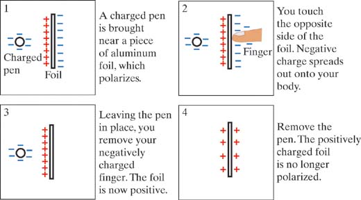
Charging by Induction
It is possible to make use of the polarizability of a conductor to make it acquire a net charge, without actually touching
a charged object. The process, called “charging by induction,” is illustrated in the sequence in Figure 15.47. In this example, a piece of neutral aluminum foil hangs from a neutral insulating tape. You charge a plastic pen by rubbing
it on wool, and bring it near the left side of the neutral foil.
Effect of Humidity on Tapes
Isolated atoms are always symmetrical and unpolarized unless an external charge shifts the electron cloud and makes an induced
dipole. However, some molecules are permanently polarized even in the absence of an external charge, and this leads to important
physical and chemical effects.
For example, water molecules are permanently polarized. The water molecule (H
2O) is not spherically symmetrical but has both hydrogen atoms off to one side of the oxygen atom. In Figure 15.48 the δ
+ and δ
− symbols are used to indicate that slight shifts of the electron clouds to the right leave the right side of the molecule
a bit negative and the left side a bit positive, so the water molecule is a permanent dipole.
|
|
|
|
|
| Figure 15.48 |
A water molecule is a permanent dipole.
|
|
|
|
|
Many of water's unusual chemical and physical properties are due to this structure. In particular, the charged ends can bind
to ions, which is why many chemicals dissolve well in water.
When water molecules in the air strike a surface they sometimes become attached to the surface, probably because the charged
ends bind to the surface. A film of water builds up on all surfaces. Pure water is a very poor conductor but does contain
small amounts of mobile H+ and H− ions. More important, the water dissolves surface contaminants such as salt, and the impure water provides an effective path
for charges to spread onto neighboring objects. After a while a charged surface loses its original charge, so experiments
with charged objects work better when the humidity is low.
|
When the Field Concept is less Useful |
|
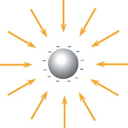
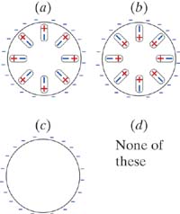
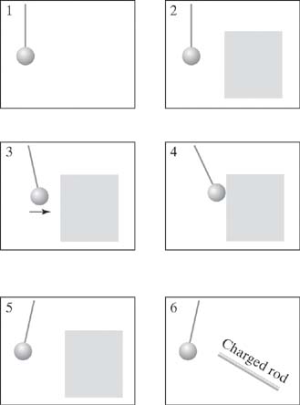
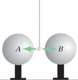
If we place a particle with very little charge
q near this charged sphere (a single proton, for example), it hardly alters the distribution of charge on the metal sphere.
We can reliably calculate the small force on the small charge as

, where

is the electric field we calculated in the absence of the small additional charge
q.
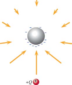
However, if we place a particle with a big charge
Q near the sphere, the sphere polarizes to a significant extent (Figure 15.50). We show the electric field due solely to the new charge distribution on the sphere (we don't show the large additional
contribution to the net electric field due to
Q). Clearly, the force on
Q is not simply
Q times the
original , but
Q times a significantly larger field.
|
|
|
|
|
| Figure 15.50 |
Electric field due to the polarized sphere.
|
|
|
|
|
With these effects in mind, we need to qualify our previous method for measuring electric field, in which we measure the force
exerted on a charge
q and determine the force per unit charge:
This procedure is valid only if
q is small enough not to disturb the arrangement of other charges that create
.
Since no object can have a charge smaller than e (the charge of a proton), sometimes it is not possible to find a charge small enough that it doesn't disturb the arrangement
of source charges. In this case, we can't measure the electric field without changing the field!
On the other hand, if we know the locations of the source charges, we can calculate the electric field at a location, by applying
the superposition principle and adding up the contributions of all the point charges that are the sources of the field:
If even the smallest possible charge
e would disturb this arrangement of source charges, we can't use the calculated field to predict the force that would act on
a charge placed at this location. However, we could use the calculated field to predict the polarization of a neutral atom
placed at that location, because a neutral atom, even if (slightly) polarized, would disturb the existing arrangement of source
charges much less than a charged object would.
Another way to improve the measurement would be to measure

for a positive
q and also measure
for a negative
q, and average the results. A negative charge would polarize the sphere in Figure 15.49 in such a way as to reduce rather than increase the value of
, by pushing the negative charges on the sphere farther away.
|
Summary |
|
|
Net charge
The net charge of an object is the sum of the charges of all of its constituent particles. An object with a net charge of
zero is called “neutral.”
Conservation of charge
The net charge of a system plus the net charge of its surroundings cannot change.
Polarization of an atom or molecule produces an induced dipole
(where p is the dipole moment and a is the atomic polarizability).
Insulator
An insulator has no mobile charges.
Conductor
A conductor contains mobile charges that can move through the material.
The average drift speed
of a mobile charged particle in a conductor is directly proportional to the magnitude of the net electric field inside the
material. The proportionality constant
u is called the “mobility” and has units of (m/s)/(N/C). Different materials have different mobilities.
Metal
A metal is a conductor. It has a mobile electron sea, spread throughout the object, like an ideal gas.
|
|
| |
Conductor
|
Insulator
|
|
Mobile charges
|
Yes
|
No
|
|
Polarization
|
Entire sea of mobile charges moves
|
Individual atoms or molecules polarize
|
|
Equilibrium
|
inside
|
nonzero inside
|
|
Location of excess charge
|
Only on surface
|
Anywhere on or inside material
|
|
Distribution of excess charge
|
Spread out over entire surface
|
Located in patches
|
|
|
|
|
|
|
|
inside a conductor in equilibrium.
Excess charges move to the surface of a conductor.
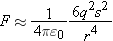
Force between a point charge and a neutral atom is proportional to 1/
r5:
|
Basic Experiments |
|
|
|
Is Invisible Tape Electrically Charged?
When you pull a long piece of invisible tape off a roll, it often curls up or sticks to your hand. We will do some simple
experiments with invisible tape.
Obtain a roll of invisible tape, such as Scotch® brand Magic™ Tape or a generic brand. It must be the kind of tape that almost disappears when you smooth it down on a surface, not ordinary
cellophane tape.
Our first task is to determine whether or not a piece of invisible tape might be electrically charged.
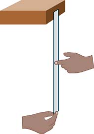
If an object has a net electric charge, it should create an electric field in the surrounding space. Another charged object
placed nearby should therefore experience an electric force. If we observe a change in an object's momentum, we can conclude
that a force acts on the object.
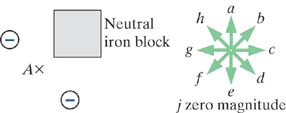
We know that the electric field of a point charge has these characteristics:
|
|
|
The magnitude of is proportional to the amount of charge.
|
|
|
|
The magnitude of decreases with distance from the charge.
|
|
|
|
The direction of is directly away from or toward the source charge.
|
|
Therefore, since  , the electric force on object 2 should have the same properties. In addition, we should be able to observe both attraction
and repulsion, since charges of different sign will be affected differently by a particular field.
We will observe the interactions of two pieces of invisible tape, and see whether they meet the criteria listed above.
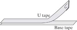
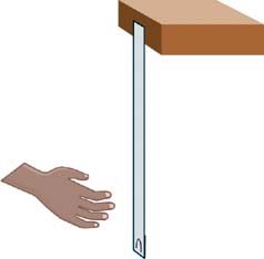
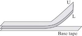
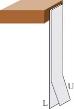
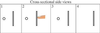
Preparing a U Tape
|
|
How to Prepare a U Tape
|
|
|
|
Stick a strip of tape with a handle down onto a smooth flat surface such as a desk. This is a “base” tape.
|
|
|
|
Smooth this base tape down with your thumb or fingertips. This base tape provides a standard surface to work from. (Without
this base tape, you get different effects on different kinds of surfaces.)
|
|
|
|
|
|
|
|
Smooth the upper tape down well with your thumb or fingertips.
|
|
|
|
Write U (for Upper) on the handle of the upper tape.
|
|
|
|
With a quick motion, pull the U tape up and off the base tape, leaving the base tape stuck to the desk.
|
|
|
|
|
|
|
|
If the tape is in good condition and the room is not too humid, you should find that there is an attraction between the hanging
strip of tape and your hand when you get close to the tape. If there is no attraction, remake the U tape.
|
|
Experimental technique: try to handle the tapes only by their ends while you are doing an experiment.
|
|
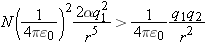
| 15.EXP.13 |
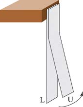
Interaction of Two U Tapes
|
|
(a)
|
If U tapes are electrically charged, how would you expect two U tapes to interact with each other? Would you expect them to
repel each other, attract each other, or not to interact at all? Make a prediction, and briefly state a reason.
|
|
|
(b)
|
Make two U (“upper”) tapes by following the procedure detailed above. Make sure that both tapes interact with your hand. Hang
one on the edge of a desk. Bring the second U tape near the hanging U tape. Since the hanging tape is attracted to your hands,
try to keep your hands out of the way. For example, you might approach the vertically hanging tape with the other tape oriented
horizontally, held by two hands at its ends. What happens?
You should have seen the two U tapes repel each other. If you did not observe repulsion, try remaking the U tapes (or making
new ones, both from the same roll of invisible tape). It is important to see this effect before continuing further.
|
|
|
|
|
|
Making a Tape Not Interact
You may have already discovered that if you handle a U tape too much, it no longer repels another U tape. Next we will learn
a systematic way for making this happen.
|
|
|
Make sure that you have an active U tape, which is attracted to your hand.
|
|
|
|
|
|
|
|
You should find that the U tape no longer interacts with your hand. If it still does, repeat the process.
|
|
This is a little odd; if the U tape was originally electrically charged, the charges would presumably have been on its sticky
side. However, by running a finger along the other side (the slick side) we have apparently “neutralized” it—it now appears
uncharged. It will be a while before we can explain this peculiar effect, but now we have a useful way to neutralize a U tape.
|
|
| 15.EXP.14 |
Is This an Electric Interaction?
To decide whether the interaction between two U tapes is or is not an electric interaction, we will see whether it obeys the
criteria for an electric interaction. (As is done throughout the scientific community, it is important to compare your results
to the results of other experimenters.)
|
|
|
|
|
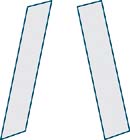
| Figure 15.55 |
Two U tapes repel each other.
|
|
|
|
|
|
|
(a)
|
Does the force act along a line connecting the two tapes? Think of a way to determine whether or not the force between two
tapes acts along a line drawn from one object to the other, and do the experiment. What did you find? (What would you see
if this were not the case?)
|
|
|
(b)
|
Does the force decrease rapidly as the distance between the tapes increases? How can you determine this?
|
|
|
(c)
|
Is the force proportional to the amounts of both charges? Design and carry out an experiment to test this. One way to vary
the amount of charge on a tape is to neutralize part of one of the tapes, by running your finger along the length of the slick
side of the tape, being careful that your finger touches only a portion of the width of the tape. What do you observe?
|
|
The real world is messy! You may have noted several difficulties in making your measurements. For example, the tapes are both
attracted to your hand, and also repel each other. If you tried to use a ruler to measure the distance between the tapes,
you might have found that the tapes are attracted to the ruler, too.
|
|
|
|
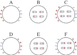
Unlike Charges
So far we have observed that two U tapes repel each other, that the force acts along a line between the tapes, that the strength
of the repulsion decreases as the tapes get farther away from each other, and that the strength of the interaction depends
on the amount of charge on the tape. These observations are consistent with the hypothesis that the U tapes are electrically
charged and that all U tapes have like electric charge.
Perhaps you reasoned along these lines: We don't know how the U tape became charged, but if the tapes started out neutral,
maybe the U tape pulled some charged particles off of the lower tape (or vice versa). So now the lower tape should have an
equal amount of charge, of the opposite sign.
Making an L Tape
Here is a reproducible procedure for making an L tape, whose charge is unlike the charge of a U tape:
Repeating exactly the same procedure, make another pair of tapes so that you have at least two U tapes and two L tapes. Before
separating the tapes from each other, always remember to make sure that the tapes are not attracted to your hand.
The principle of conservation of charge states that if the pair has a total charge of zero before separation, the two tapes
will have a total charge of zero after separation: one tape will have a charge of +q and the other a charge of −q. However, if the total charge before separation is nonzero and positive (say), the separated tapes could both have positive
charge, as long as their individual charges add up to the original amount.
|
|
| 15.EXP.15 |
Observations of L and U Tapes
You should now have two L tapes and two U tapes. Make sure that both the U tapes and the L tapes are active (attracted to
your hand).
|
|
(a)
|
If an L tape is indeed electrically charged, and its charge is unlike the charge on a U tape, what interaction would you predict between an L tape and a U tape?
|
|
|
(b)
|
What interaction do you observe between an L tape and a U tape?
|
|
|
(c)
|
What interaction would you predict between two L tapes?
|
|
|
(d)
|
What interaction do you observe between two L tapes?
|
|
|
(e)
|
Is the pattern of interactions consistent with the statement: “Like charges repel; unlike charges attract”?
|
|
|
|
|
|
A U Tape and an L Tape: Distance Dependence of Attraction
If U and L tapes are electrically charged, then we would expect the strength of the attractive interaction to decrease as
the distance between the tapes increases. Make the same sort of observations you made with two U tapes.
|
|
| 15.EXP.16 |
Distance Dependence of Force between U and L Tapes
Move a U tape very slowly toward a hanging L tape. Observe the deflections of the tapes from the vertical, at several distances
(for example, the distance at which you first see attraction, half that distance, etc.) The deflections of the tapes away
from the vertical is a measure of the strength of the interaction.
|
|
(a)
|
Does the force decrease rapidly as the distance between the tapes increases?
|
|
|
(b)
|
Why is this measurement more difficult with a U and an L tape than with two U tapes?
|
|
Summary and Conclusions: U and L Tapes
Let's summarize the observations and try to conclude, at least tentatively, whether U and L tapes are electrically charged.
Presumably you have observed the following:
|
|
|
There are two kinds of charge, called “ + ” and “ − ”.
|
|
|
|
Like charges repel, unlike charges attract.
|
|
|
|
The electric force
|
|
▪
|
acts along a line between the charges,
|
|
|
▪
|
decreases rapidly as the distance between the charges increases, and
|
|
|
▪
|
is proportional to the amounts of both charges.
|
|
|
|
Our observations of U and L tapes seem to be consistent with a description of the electric interactions between charged objects.
We tentatively conclude that U and L tapes are electrically charged, and have unlike charges.
|
|
|
|
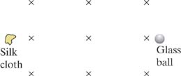
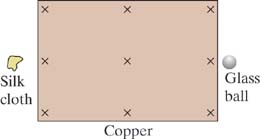
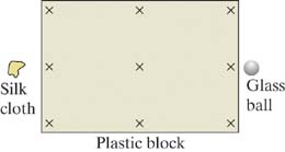
How a Plastic Comb or Pen Becomes Charged
Charged objects, such as invisible tape, are negatively charged if they have more electrons than protons, and positively charged
if they have fewer electrons than protons. Are U tapes positively or negatively charged? How can we tell? Charging an object
in a standard manner gives us a “litmus test.”
It is known that if you rub a glass rod with silk, the glass rod becomes positively charged and the silk negatively charged.
Likewise, if you rub a clear plastic object such as a pen through your hair (or with fur, wool, or even cotton), the plastic
ends up having a negative charge and so repels electrons. A similar process occurs when you separate one tape from another.
See Section 15.2 for a discussion of how objects become charged through rubbing or contact.
|
|
| 15.EXP.17 |
Determining the Charge on U and L Tapes
Prepare a U tape and an L tape, and hang them from your desk. Test them with your hand to make sure they are both charged.
Rub a plastic pen or comb on your hair (clear plastic seems to charge best), or on a piece of cotton or wool, and bring it
close to each tape. You should observe that one of the tapes is repelled by the pen, and one is attracted to it.
Knowing that the plastic is negatively charged, what can you conclude about the sign of the electric charge on U tapes? On
L tapes?
These results may be reversed if you try a different brand of “invisible tape.” Be sure to compare your results with those
of other students. Make sure you all agree on the assignment of “+” and “−” labels to your tapes. (If other groups are using
different brands of tape, you may disagree on whether U tapes or L tapes are positive, but the electric interactions between
your + tapes and their − tapes should be repulsive!)
In any of your experiments, did you find any objects, other than tapes or a charged comb or pen, that repelled a U or L tape?
If so, those objects must have been charged. List these objects and whether the charge was + or −.
|
|
|
|
Amount of Charge on a Tape
We have concluded that U tapes and L tapes are electrically charged, but we have no idea how much charge is on one of the
charged tapes—we don't even know an approximate order of magnitude for this quantity. Even a rough measurement of the amount
of charge on a tape would be useful, because it would give us a feel for the amount of charge there might be on an ordinary
object that is observed to interact electrically with other objects. Therefore the following experiment is an important one.
|
|
| 15.EXP.18 |
Amount of Excess Charge on a Tape
In this problem you will design and carry out an experiment to determine the approximate number of excess electron charges
on the surface of a negatively charged tape.
Initial estimates
Since we do not know what order of magnitude to expect for our answer, it is important to put upper and lower bounds on reasonable
answers.
|
|
(a)
|
What is the smallest amount of excess charge that a tape could possibly have?
|
|
|
(b)
|
What is the largest amount of excess charge a tape could possibly have?
|
|
Design and perform an experiment
A centimeter ruler is printed on the inside back cover of this textbook. A piece of half-inch-wide (1.2 cm) invisible tape,
20 cm long (8 inches), has a mass of about 0.16 grams.
|
| (c) |
Make a clear and understandable diagram of your experimental setup, indicating each quantity you measured. Report all measurements
you made.
|
|
Analyze the results
|
| (d) |
Clearly present your physical analysis of your data. Make an appropriate diagram, labeling all vector quantities. Reason from
fundamental physics principles. Explicitly report any simplifying assumptions or approximations you have made in your analysis.
Report two quantities:
|
|
▪
|
The amount of charge on a tape, in coulombs
|
|
|
▪
|
The number of excess electrons to which this charge corresponds
|
|
|
|
Present your analysis clearly. Your reasoning must be clear to a reader.
|
| (e) |
Estimate whether the true amount of excess charge is larger or smaller than the value you calculated from your experimental
data. Explain your reasoning briefly.
|
|
Is this a lot of charge?
Does your answer suggest that it is a common event or a rare event for a molecule to gain an extra electron?
|
| (g) |
If the electric field at a location in air exceeds 3 × 10 6 N/C, the air will become ionized and a spark will be triggered. In Chapter 16 we will see that the electric field in a region very close to a uniformly charged disk or plate depends approximately only
on the charge Q per unit area A:
|
|
Use this model (or make a different but justifiable simplifying assumption) to calculate the magnitude of the electric field
at a location in the air very close to your tape (less than 1 mm from the surface of the tape). How does it compare to the
electric field needed to trigger a spark in the air?
|
|
|
|
Interaction of Charges and Neutral Matter
We have focused on the interactions of U and L tapes with other U and L tapes. Let's look more broadly at the interactions
of charged tapes with other objects.
|
|
| 15.EXP.19 |
Interactions of U and L Tapes with Other Objects
Which other objects (paper, metal, plastic, etc.) have an attractive interaction with a hanging U or L tape, and which objects
have a repulsive interaction? Which objects have no interaction? Record the objects you try and the interactions observed.
The attraction of both U and L tapes to your hand, and to many other objects, is deeply mysterious. The net charge of a neutral
object is 0, so your neutral hand should not make an electric field that could act on a charged tape; nor should your neutral
hand experience a force due to the electric field made by a charged tape. Nothing in our statement of the properties of electric
interactions allows us to explain this attraction!
|
|
|
|
|
Additional Experiments |
|
|
|
Observing Interactions with Dipoles
You can also use charged tapes to observe the behavior of a dipole.
There is a twist (torque) that tends to align the dipole along the line connecting the charge Q and the center of the dipole, with the negative end of the dipole closer to the single positive charge. The dipole has a
nonzero net force acting on it that makes it move toward the positive charge.
|
|
| 15.EXP.20 |
An Electric “Compass”
Make a tall dipole and observe the motion. Take a + tape and a − tape and stick them together, overlapping them only enough
to hold them together. Avoid discharging the tapes with too much handling. Hang the combination from a thread or a hair.
Now approach the tapes with a charged object and admire how sensitive a charge detector you have made! Slowly move the charged
object all around the dipole and observe how the dipole tracks the object.
If you draw an appropriately labeled arrow on the tape, you have an electric “compass” that points in the direction of electric
field.
|
|
|
| 15.EXP.21 |
Observing Attraction of Like-Charged Objects (!)
Because of the very rapid 1/ r5 increase in the attraction to neutral matter at short distances, it is sometimes the case that at short distances the attractive
effect can actually overcome the repulsion between like-charged objects. Specifically, it could be that
where q1 and q2 are the excess charges on the surfaces of the two tapes, and N is the total number of neutral atoms in tape 2 (since each neutral atom participates in the attraction.) As can be seen by
dividing the inequality by q1, you can enhance the effect by making q1 be significantly larger than q2, so you might wish to partially discharge one of the tapes.
|
|
|
|
|
| Figure 15.61 |
A dipole made from U and L tapes.
|
|
|
|
|
Try it! Hold one of the U tapes horizontally, with its slick side facing away from you and toward the slick side of the hanging
tape. Move toward the hanging tape and check that the hanging tape is repelled as you approach. Then move close enough so
that the tapes touch each other (a partner may have to hold the bottom of the hanging tape in order to be able to get very
close).
You may be able to detect some slight attraction when the tapes are very close together or touch each other, despite the fact
that the tapes repel at longer distances. Do you see such an effect? The effect is quite easy to see in the interaction between
a highly charged Van de Graaff generator and a charged tape.
|
|
|
| 15.EXP.22 |
Interaction through a Piece of Paper
Can you observe repulsion occurring right through the intervening paper? This is difficult, because the paper attracts the
hanging tape, which masks the repulsion due to the other tape. You can heighten the sensitivity of the experiment by moving
the tape rhythmically toward and away from the hanging tape, as though you were pushing a swing. This lets you build up a
sizable swing in the hanging tape even though the repulsive force is quite small, because you are adding up lots of small
interactions. Using rhythmic movements, are you able to observe repulsion through the intervening paper?
The effect is especially hard to observe if you have weak repulsion due to high humidity. The farther away you can detect
repulsion, the better, because the competing attraction falls off rapidly with distance. Under good conditions of low humidity,
when tapes remain strongly charged and repulsion is observable with the tapes quite far apart from each other, it is possible
to see repulsion with the paper in place, showing that electric field does go right through intervening matter. You have seen
evidence of this when you observed attraction between a tape and your hand even when you approached the slick side of the
tape.
|
|
|
| 15.EXP.23 |
Is Tape a Conductor or an Insulator?
Prepare a hanging tape that has the top half charged and the bottom half uncharged. After a second or two, check to see whether
the bottom half of the tape has become charged.
Based on this observation, is tape a conductor or an insulator? That is, are the charges free or bound? Explain fully and
rigorously how your observations justify your conclusion. (Hint: Draw a diagram showing what effect the charges on the upper
half of the tape have on each other and on charges inside the tape, and reason through what will happen if any of these charges
are free to move.)
|
|
|
| 15.EXP.24 |
Discharging a Tape
The previous exercise suggests that a key element in neutralizing a tape is the salt solution on the surface of your finger.
Design one or more experiments you can do to confirm or reject this explanation of discharging a tape.
|
|
|
| 15.EXP.25 |
Charging by Induction
Now carry out the following operations exactly as specified:
|
|
1.
|
Make sure that the tape and foil are uncharged (touch the foil, and rub the slick side of the tape).
|
|
|
2.
|
Have a partner hold onto the bottom tape to keep the foil from moving.
|
|
|
3.
|
Bring a charged plastic pen or comb very close to the foil, but don't touch the foil with the plastic.
|
|
|
4.
|
While holding the plastic near the foil, tap the back of the foil with your finger.
|
|
|
5.
|
Move your finger away from the foil, then move the plastic away from the foil.
|
|
You should find that the metal foil is now strongly charged. This process is called “charging by induction.” Now touch the
charged aluminum foil with your finger and observe that this discharges the foil, as predicted by our earlier discussion.
Make sure you have the sign of the charges right. In each diagram show charge distributions, polarization, movement of charges,
and so on. For each frame, explain briefly what happens. Remember that excess charges on the metal foil can only be on the
surface.
This process is called charging by induction because the entire piece of foil becomes an induced dipole when it is polarized
by the external charge. Charging by induction makes it possible to charge a metal without touching the external charge to
the metal.
Explain the process of discharging the metal foil by touching it, using the same kind of time-sequence “comic strip” diagrams
you used in the previous exercise. Illustrate the important aspects of each step in the process. Include any changes to your
body as well as to the foil. Be precise in your use of words.
|
|
|
| 15.EXP.26 |
A Water Film as a Conductor
Prepare a hanging tape that has the top half charged and the bottom half uncharged. Let it hang while you do other work, but
check every few minutes to see what has happened in the two halves. What do you predict will happen to the state of charge
in the two halves? What do you observe over a period of many minutes? (If the room is very dry or very wet you may not be
able to see this effect.)
Suppose you were to breathe heavily through your mouth onto the slick and sticky sides of a short section in the middle of
a long charged tape. Your breath is very moist. What do you predict you would find immediately afterward? Try the experiment—what
do you observe? (Repeat if you see no effect.)
|
|
|
| 15.EXP.27 |
Transferring Charge by Contact
Next make the two foils touch each other, being careful not to touch either foil with your fingers. Note the approximate strength
of the interaction that there is now between the plastic and each foil.
Compared with the situation before the two foils touched, what sign of charge, and roughly how much, is there now on each
foil? Discuss this fully with your partners, and convince yourselves that you understand the process. Make a written explanation,
including appropriate diagrams.
What would you expect to happen if one piece of foil were much larger than the other?
|
|
|
|
|
Exercises and Problems |
|
|
|
Section 15.1 |
|
| 15.X.28 |
Which statements about a neutral atom are correct? Select all that apply.
|
|
(A)
|
A neutral atom is composed of both positively and negatively charged particles.
|
|
|
(B)
|
The positively charged particles in the nucleus are positrons.
|
|
|
(C)
|
The electrons are attracted to the positively charged nucleus.
|
|
|
(D)
|
Positively charged protons are located in the tiny, massive nucleus.
|
|
|
(E)
|
The radius of the electron cloud is twice as large as the radius of the nucleus.
|
|
|
(F)
|
The negatively charged electrons are spread out in a “cloud” around the nucleus.
|
|
|
|
|
|
|
|
|
Section 15.2 |
|
| 15.X.29 |
Which of the following could be reasonable explanations for how a piece of invisible tape gets charged? Select all that apply.
|
|
(A)
|
Protons are pulled out of nuclei in one tape and transferred to another tape.
|
|
|
(B)
|
Charged molecular fragments are broken off one tape and transferred to another.
|
|
|
(C)
|
Electrons are pulled out of molecules in one tape and transferred to another tape.
|
|
|
(D)
|
Neutrons are pulled out of nuclei in one tape and transferred to another tape.
|
|
|
|
|
|
|
| 15.X.32 |
Jill stuck a piece of invisible tape down onto another piece of tape. Then she yanked the upper tape off the lower tape, and
she found that this upper tape strongly repelled other upper tapes and was charged positive. Jack ran his thumb along the
slick (upper) side of the upper tape, and the tape no longer repelled other upper tapes. Jill and Jack explained this by saying
that Jack rubbed some protons out of the carbon nuclei in the tape.
Give a critique of their explanation. If Jill's and Jack's explanation is deficient, give a physically possible explanation
for why the upper tape no longer repelled other upper tapes. Include explanatory diagrams.
|
|
|
|
|
|
|
Section 15.3 |
|
| 15.X.33 |
You rub a clear plastic pen with wool, and observe that a strip of invisible tape is attracted to the pen. Assuming that the
pen has a net negative charge, which of the following could be true? Select all that apply.
|
|
(A)
|
The tape might be negatively charged.
|
|
|
(B)
|
The tape might be positively charged.
|
|
|
(C)
|
The tape might be uncharged.
|
|
|
(D)
|
There is not enough information to conclude anything.
|
|
|
|
|
|
|
| 15.X.34 |
There is a region where an electric field points to the right, due to charged particles somewhere. A neutral carbon atom is
placed inside this region. Draw a diagram of the situation, and use it to answer the following question: Which of the following
statements are correct? Select all that apply.
|
|
(A)
|
Because the net charge of the carbon atom is zero, it cannot be affected by an electric field.
|
|
|
(B)
|
The electron cloud in the carbon atom shifts to the left.
|
|
|
(C)
|
The neutral carbon atom polarizes and becomes a dipole.
|
|
|
(D)
|
The nucleus of the carbon atom shifts to the left.
|
|
|
|
|
|
|
| 15.X.35 |
A charged particle with charge q1 is a distance r from a neutral atom, as shown in Figure 15.66.
|
|
(a)
|
If q1 is negative which diagram (1–10) in Figure 15.67 best shows the charge distribution in the neutral atom in this situation?
|
|
|
(b)
|
Which of the arrows ( a–j) in Figure 15.68 best indicates the direction of the electric field at the location of the charged particle, made by the polarized neutral
atom?
|
|
|
(c)
|
Which of the arrows (a–j) in Figure 15.68 best indicates the direction of the force on the charged particle, due to the polarized neutral atom?
|
|
|
(d)
|
Which of the arrows (a–j) in Figure 15.68 best indicates the direction of the force on the polarized neutral atom, due to the charged particle?
|
|
|
|
|
|
|
| 15.X.36 |
Atom A is easier to polarize than atom B. Which atom, A or B, would experience a greater attraction to a point charge a distance r away?
|
|
(A)
|
A
|
|
|
(B)
|
B
|
|
|
(C)
|
Same
|
|
|
(D)
|
The polarization does not matter.
|
|
|
|
|
|
|
| 15.X.38 |
Which observation provides evidence that two objects have the same sign charge?
|
|
(A)
|
The two objects repel each other.
|
|
|
(B)
|
The two objects attract each other.
|
|
|
(C)
|
The two objects do not interact at all.
|
|
|
(D)
|
The strength of the interaction between the two objects depends on distance.
|
|
|
|
|
|
|
| 15.X.39 |
Is the following statement true or false? If true, what principle makes it true? If false, give a counterexample or say why.
See Figure 15.69.
“The electric field Epoint at the center of an induced dipole, due to the point charge, is equal in magnitude and opposite in direction to the electric
field Edipole at the location of the point charge, due to the induced dipole.”
|
|
|
|
|
| 15.P.41 |
A large positive charge pulls on a distant electron. How does the net force on the electron change if a slab of glass is inserted between the large positive charge and the electron? Does the
net force get bigger, smaller, or stay the same? Explain, using only labeled diagrams.
(Be sure to show all the forces on the electron before determining the net force on the electron, not just the force exerted by the large positive
charge. Remember that the part of the net force on the electron contributed by the large positive charge does not change when
the glass is inserted: the electric interaction extends through matter.)
|
|
|
|
|
| 15.P.42 |
Try rubbing a plastic pen through your hair, and you'll find that you can pick up a tiny scrap of paper when the pen is about
one centimeter above the paper. From this simple experiment you can estimate how much an atom in the paper is polarized by
the pen! You will need to make several assumptions and approximations. Hints may be found at the end of the chapter.
|
|
(a)
|
Suppose that the center of the outer electron cloud (q = −4e) of a carbon atom shifts a distance s when the atom is polarized by the pen. Calculate s algebraically in terms of the charge Q on the pen.
|
|
|
(b)
|
Assume that the pen carries about as much charge Q as we typically find on a piece of charged invisible tape. Evaluate s numerically. How does this compare with the size of an atom or a nucleus?
|
|
|
(c)
|
Calculate the polarizability a of a carbon atom. Compare your answer to the measured value of 1.96 × 10−40C · m/(N/C) (T. M. Miller and B. Bederson, “Atomic and molecular polarizabilities: a review of recent advances,” Advances in Atomic and Molecular Physics, 13, 1–55, 1977).
|
|
|
(d)
|
Carefully list all assumptions and approximations you made.
|
|
Hints
|
|
(a)
|
(a1) What must the force on a single carbon atom in the paper be at the moment the paper is lifted by the pen? (a2) You know
how to calculate the force on a point charge due to a dipole. How does this relate to the force on the dipole by the point
charge? In this problem, is there something you can model as a dipole and something else you can model as a point charge?
|
|
|
(b)
|
Note that the dipole moment (p = qs) of a polarized atom or molecule is directly proportional to the applied electric field. In this case the charged pen is
generating the applied electric field.
|
|
|
|
|
|
|
| 15.P.43 |
An electron and a neutral carbon atom are initially 1 × 10 −6 apart (about 10000 atomic diameters), and there are no other particles in the vicinity. The polarizability of a carbon atom
has been measured to be α = 1.96 × 10 −40 C · m/(N/C).
|
|
(a)
|
Calculate the initial magnitude and direction of the acceleration of the electron. Explain your steps clearly. Pay particular
attention to clearly defining your algebraic symbols. Don't put numbers into your calculation until the very end.
|
|
|
(b)
|
If the electron and carbon atom were initially twice as far apart, how much smaller would the initial acceleration of the
electron be?
|
|
|
|
|
|
|
| 15.P.44 |
Two identical permanent dipoles, each consisting of charges + q and − q separated by a distance s, are aligned along the x axis, a distance r from each other, where r >> s. Show all of the steps in your work, and briefly explain each step.
|
|
(a)
|
Draw a diagram like the one shown in Figure 15.70. Draw vectors showing all individual forces acting on each particle, and draw heavier vectors showing the net force on each
dipole.
|
|
|
(b)
|
Show that the magnitude of the net force exerted on one dipole by the other dipole is
|
|
|
|
|
|
|
|
|
Section 15.4 |
|
| 15.X.47 |
A charged piece of invisible tape is brought near your hand, as shown in Figure 15.72. Your hand is initially neutral.
|
|
(a)
|
If the tape is negatively charged, which of the diagrams 1–10 in Figure 15.73 best shows the polarization of a neutral molecule in your hand?
|
|
|
(b)
|
Which arrow in Figure 15.74 best indicates the direction ( a–j) of the electric field at the location of the tape due to the large number of polarized molecules in your hand?
|
|
|
(c)
|
Which arrow in Figure 15.74 best indicates the direction (a–j) of the force on the tape due to the polarized molecules in your hand?
|
|
|
(d)
|
Which arrow in Figure 15.74 best indicates the direction (a–j) of the force on your hand due to the charged tape?
|
|
|
|
|
|
|
| 15.P.48 |
A dipole consisting of two oppositely charged balls connected by a wooden stick is located as shown in Figure 15.75. A block of plastic is located nearby, as shown. Locations B, C, and D all lie on a line perpendicular to the axis of the dipole, passing through the midpoint of the dipole.
Before selecting answers to the following questions, draw your own diagram of this situation, showing all the fields and charge
distributions requested.
Answer the following questions by selecting either a direction ( a– j) or an orientation of a polarized molecule (1–10) from the diagrams in Figure 15.76.
|
|
|
|
|
(a)
|
Which of the arrows (a–j) best indicates the direction of the electric field at location C due only to the dipole?
|
|
|
(b)
|
Which of the arrows (a–j) best indicates the direction of the electric field at location D due only to the dipole?
|
|
|
(c)
|
Which of the diagrams (1–10) best indicates the polarization of a molecule of plastic at location C?
|
|
|
(d)
|
Which of the diagrams (1–10) best indicates the polarization of a molecule of plastic at location D?
|
|
|
(e)
|
Which of the following statements is correct?
|
|
(1)
|
A molecule located at C would not be polarized at all.
|
|
|
(2)
|
The polarization of a molecule located at D would be the same as the polarization of a molecule located at C.
|
|
|
(3)
|
A molecule located at D would be polarized more than a molecule located at C.
|
|
|
(4)
|
A molecule located at D would be polarized less than a molecule located at C.
|
|
|
|
|
(f)
|
Which of the arrows (a–j) best indicates the direction of the electric field at location B due only to the dipole?
|
|
|
(g)
|
Which of the arrows (a–j) best indicates the direction of the electric field at location B due only to the plastic block? The magnitude of the electric field at B due to the plastic is less than the magnitude of the electric field at B due to the dipole.
|
|
|
(h)
|
Which of the arrows (a–j) best indicates the direction of the net electric field at location B?
|
|
|
(i)
|
Which of the following statements is correct?
|
|
(1)
|
The electric field at B due only to the dipole would be larger if the plastic block were not there.
|
|
|
(2)
|
The electric field at B due only to the dipole would be the same if the plastic block were not there.
|
|
|
(3)
|
The electric field at B due only to the dipole would be smaller if the plastic block were not there.
|
|
|
(4)
|
The electric field at B due only to the dipole would be zero if the plastic block were not there.
|
|
|
|
|
(j)
|
Using the diagrammatic conventions discussed in the text, a student drew the diagram in Figure 15.77 to help answer the questions asked above. Which of the following statements about the student's diagram are true? Check all
that apply.
|
|
(1)
|
The direction of polarization of the plastic block is wrong.
|
|
|
(2)
|
The diagram is correct; this is just a different way of drawing the polarization.
|
|
|
(3)
|
The diagram shows mobile charges; this is wrong because an insulator does not have mobile charged particles.
|
|
|
|
|
|
|
|
|
|
|
Sections 15.5 |
|
| 15.X.49 |
A negatively charged iron block is placed in a region where there is an electric field downward (in the − y direction) due to charges not shown. Which of the diagrams (a–f) in Figure 15.78 best describes the charge distribution in and/or on the iron block?
|
|
|
|
|
| 15.X.50 |
A neutral copper block is polarized as shown in Figure 15.79, due to an electric field made by external charges (not shown). Which arrow ( a– j) in Figure 15.79 best indicates the direction of the net electric field at location B, which is inside the copper block?
|
|
|
|
|
| 15.X.51 |
Two small, negatively charged plastic spheres are placed near a neutral iron block, as shown in Figure 15.80. Which arrow ( a– j) in Figure 15.80 best indicates the direction of the net electric field at location A?
|
|
|
|
|
| 15.X.52 |
|
|
(a)
|
Which of the diagrams (A–F) in Figure 15.81 correctly displays the polarization of a metal sphere by an electric field that points to the left, using the conventions discussed in this chapter?
|
|
|
(b)
|
Which of the diagrams (A–F) in Figure 15.81 correctly displays the polarization of a plastic sphere by an electric field that points to the left, using the conventions discussed in this chapter?
|
|
|
|
|
|
|
| 15.X.53 |
Which of the following are true? Select all that apply.
|
|
(A)
|
In static equilibrium, there is no net flow of mobile charged particles inside a conductor.
|
|
|
(B)
|
The electric field from an external charge cannot penetrate to the center of a block of iron.
|
|
|
(C)
|
The net electric field inside a block of aluminum is zero under all circumstances.
|
|
|
(D)
|
If the net electric field at a particular location inside a piece of metal is not zero, the metal is not at equilibrium.
|
|
|
(E)
|
The net electric field at any location inside a block of copper is zero if the copper block is at equilibrium.
|
|
|
|
|
|
|
| 15.X.54 |
Which of the following are true? Check all that apply. “Static equilibrium” means that no charges are flowing.
|
|
(A)
|
If the net electric field at a particular location inside a piece of metal is not zero, the metal is not at static equilibrium.
|
|
|
(B)
|
The net electric field inside a block of aluminum is zero under all circumstances.
|
|
|
(C)
|
The net electric field at any location inside a block of copper is zero if the copper block is at static equilibrium.
|
|
|
(D)
|
The electric field from an external charge cannot penetrate to the center of a block of iron.
|
|
|
(E)
|
In static equilibrium, there is no net flow of mobile charged particles inside a conductor.
|
|
|
|
|
|
|
| 15.X.60 |
Figure 15.83 shows a neutral, solid piece of metal placed near two point charges. Copy this diagram.
|
|
(a)
|
On your diagram, show the polarization of the piece of metal.
|
|
|
(b)
|
Then, at location A inside the solid piece of metal, carefully draw and label three vectors:
|
|
(1)
|
, the electric field due to − q1 |
|
|
(2)
|
 , the electric field due to + q2 |
|
|
(3)
|
 , the electric field due to all of the charges on the metal
|
|
|
|
|
(c)
|
Explain briefly why you drew the vectors the way you did.
|
|
|
|
|
|
|
| 15.X.61 |
You place a neutral block of nickel near a small glass sphere that has a charge of 2 × 10 −8 coulombs uniformly distributed over its surface, as shown in Figure 15.84.
|
|
(a)
|
About how long do you have to wait to make sure that the mobile electron sea inside the nickel block has reached equilibrium?
|
|
(1)
|
Less than a nanosecond (1 × 10⁻⁹s)
|
|
|
(2)
|
Several hours
|
|
|
(3)
|
About 1 second
|
|
|
(4)
|
About 10 minutes
|
|
|
|
|
(b)
|
In equilibrium, what is the average drift speed of the mobile electrons inside the nickel block?
|
|
(1)
|
About 1 × 10⁵ m/s
|
|
|
(2)
|
About 1 × 10⁻⁵ m/s
|
|
|
(3)
|
0 m/s
|
|
|
|
|
(c)
|
In the equation  , what is the meaning of the symbol u?
|
|
(1)
|
The density of mobile electrons inside the metal, in electrons/m3.
|
|
|
(2)
|
The mobility of an electron inside the metal, in (m/s)/(N/C).
|
|
|
(3)
|
The time it takes a block of metal to reach equilibrium, in seconds.
|
|
|
|
|
|
|
|
|
| 15.X.62 |
This question focuses on reasoning about equilibrium inside the nickel block shown in Figure 15.84. Start with these premises:
|
|
|
The definition of equilibrium inside a conductor
|
|
|
|
The relationship between average drift speed and electric field in a conductor
|
|
to reason about which situations are possible inside the nickel block at equilibrium. Some of the situations listed below are possible, some are ruled out by one premise,
and some are ruled out by two premises. If a situation is ruled out by two premises, choose both.
Case 1: and Enet = 0
|
|
(A)
|
Possible
|
|
|
(B)
|
Not possible by definition of equilibrium
|
|
|
(C)
|
Not possible because  |
|
Case 2: and 
|
|
(A)
|
Possible
|
|
|
(B)
|
Not possible by definition of equilibrium
|
|
|
(C)
|
Not possible because |
|
Case 3: and 
|
|
(A)
|
Possible
|
|
|
(B)
|
Not possible by definition of equilibrium
|
|
|
(C)
|
Not possible because |
|
Case 4: and
|
|
(A)
|
Possible
|
|
|
(B)
|
Not possible by definition of equilibrium
|
|
|
(C)
|
Not possible because |
|
Now that you have considered each case, in equilibrium, which one is the only situation that is physically possible?
|
|
(A)
|
Case 1
|
|
|
(B)
|
Case 2
|
|
|
(C)
|
Case 3
|
|
|
(D)
|
Case 4
|
|
|
|
|
|
|
| 15.X.63 |
A positively charged sphere is placed near a neutral block of nickel, as shown in Figure 15.84.
|
|
(a)
|
Which of the diagrams in Figure 15.85 best represents the equilibrium distribution of charge on the neutral nickel block?
|
|
|
(b)
|
At location P inside the nickel block the electric field due to the charged sphere is  N/C. At equilibrium, which of the following statements must be true?
|
|
(1)
|
It is not possible to determine the electric field at location P due only to charges on the surface of the nickel block.
|
|
|
(2)
|
The electric field at location P due only to charges on the surface of the nickel block is  N/C.
|
|
|
(3)
|
Because the net electric field at location P is N/C, the field at P due only to charges on the surface of the polarized nickel block must be  N/C.
|
|
|
|
|
|
|
|
|
| 15.P.64 |
|
|
(a)
|
The positively charged particle shown in diagram 1 in Figure 15.86 creates an electric field  at location A. Which of the arrows ( a– j) in Figure 15.86 best indicates the direction of at location A?
|
|
|
(b)
|
Now a block of metal is placed in the location shown in diagram 2 in Figure 15.86. Which of the arrows ( a– j) in Figure 15.86 best indicates the direction of the electric field  at location A due only to the charges in and/or on the metal block?
|
|
|
(c)
|
 is greater than  . With the metal block still in place, which of the arrows ( a– j) in Figure 15.86 best indicates the direction of the net electric field at location A?
|
|
|
(d)
|
With the metal block still in place, which of the following statements about the magnitude of , the field due only to the charged particle, is correct?
|
|
(1)
|
is less than it was originally, because the block is in the way.
|
|
|
(2)
|
is the same as it was originally, without the block.
|
|
|
(3)
|
is zero, because the electric field due to the particle can't go through the block.
|
|
|
|
|
(e)
|
With the metal block still in place, how does the magnitude of at location A compare to the magnitude of ?
|
|
|
(f)
|
Which of the arrows (a–j) in Figure 15.86 best indicates the direction of the net electric field at the center of the metal block (inside the metal)?
|
|
|
|
|
|
|
| 15.P.65 |
Two identical metal spheres are suspended from insulating threads. One is charged with excess electrons, and the other is
neutral. When the two spheres are brought near each other, they swing toward each other and touch, then swing away from each
other.
|
|
(a)
|
Explain in detail why both these swings happen. In your explanation, include clear diagrams showing charge distributions,
including the final charge distribution.
|
|
|
(b)
|
Next the spheres are moved away from each other. Then a block of plastic is placed between them as shown in Figure 15.87. The original positions of the spheres are indicated, before the plastic is placed between them. Sketch the new positions
of the spheres. Explain, including charge distributions on the spheres.
|
|
|
(c)
|
Show the polarization of a molecule inside the plastic at points A, B, C, D, and E. Explain briefly.
|
|
|
|
|
|
|
| 15.P.66 |
A small glass ball is rubbed all over with a small silk cloth and acquires a charge of +5 nC. The silk cloth and the glass
ball are placed 30 cm apart.
|
|
(a)
|
On a diagram like that shown in Figure 15.88, draw the electric field vectors qualitatively at the locations marked ×. Pay careful attention to directions and to relative
magnitudes. Use dashed lines to explain your reasoning graphically, and draw the final electric field vectors with solid lines.
|
|
|
(b)
|
Next, a neutral block of copper is placed between the silk and the glass.
On a diagram like that shown in Figure 15.89, carefully show the approximate charge distribution for the copper block and the electric field vectors inside the copper
at the ×.
|
|
|
(c)
|
The copper block is replaced by a neutral block of plastic. Carefully show the approximate molecular polarization of the plastic
block at the locations marked × in Figure 15.90.
|
|
|
(d)
|
Even if you have to state your result as an inequality, make as quantitative a statement as you can about the electric field
at the location of the glass ball and the net force on the ball when the plastic block is in place compared to when there
is no block. Explain briefly.
|
|
|
|
|
|
|
| 15.P.67 |
A metal ball with diameter of a half a centimeter and hanging from an insulating thread is charged up with 1 × 10 10 excess electrons. An initially uncharged identical metal ball hanging from an insulating thread is brought in contact with
the first ball, then moved away, and they hang so that the distance between their centers is 20 cm.
|
|
(a)
|
Calculate the electric force one ball exerts on the other, and state whether it is attractive or repulsive. If you have to
make any simplifying assumptions, state them explicitly and justify them.
|
|
|
(b)
|
Now the balls are moved so that as they hang, the distance between their centers is only 5 cm. Naively one would expect the force that one ball exerts on the other to increase by a factor of 42 = 16, but in real life the increase is a bit less than a factor of 16. Explain why, including a diagram. (Nothing but the
distance between centers is changed—the charge on each ball is unchanged, and no other objects are around.)
|
|
|
|
|
|
|
| 15.P.68 |
As shown in Figure 15.91, an electroscope consists of a steel ball connected to a steel rod, with very thin gold foil leaves connected to the bottom
of the rod (in good electric contact with the rod). The bottom of the electroscope is enclosed in a glass jar and held in
place by a rubber stopper.
|
|
(a)
|
The electroscope is brought near to but not touching a positively charged glass rod as shown in Figure 15.92. The foil leaves are observed to spread apart. Explain why in detail, using as many diagrams as necessary.
|
|
|
(b)
|
The electroscope is moved far away from the glass rod and the steel ball is touched momentarily to a metal block. The foil
leaves spread apart and stay spread apart when the electroscope is moved away from the block. As the electroscope is moved
close to but not touching the positively charged glass rod, the foil leaves move closer together. Is the metal block positive,
negative, or neutral? How do you know? Explain.
|
|
|
|
|
|
|
| 15.P.69 |
A very thin spherical plastic shell of radius 15 cm carries a uniformly distributed negative charge of −8nC(−8 × 10 −9 C) on its outer surface (so it makes an electric field as though all the charge were concentrated at the center of the sphere).
An uncharged solid metal block is placed nearby. The block is 10 cm thick, and it is 10 cm away from the surface of the sphere.
See Figure 15.93.
|
|
(a)
|
Sketch the approximate charge distribution of the neutral solid metal block.
|
|
|
(b)
|
Draw the electric field vector at the center of the metal block that is due solely to the charge distribution you sketched
(that is, excluding the contributions of the sphere).
|
|
|
(c)
|
Calculate the magnitude of the electric field vector you drew. Explain briefly. If you must make any approximations, state
what they are.
|
|
|
|
|
|
|
| 15.P.70 |
Two plastic balls are charged equally and positively and held in place by insulating threads, as shown in Figure 15.94.
They repel each other with an electric force of magnitude F. Then an uncharged metal ball is held in place by insulating threads between the balls, closer to the left ball. State what
change (if any) there is in the net electric force on the left ball and on the net electric force on the right ball. Show
relevant force vectors. Also show the charge distribution on the metal ball. Explain briefly but completely.
|
|
|
|
|
| 15.P.71 |
A thin, hollow spherical plastic shell of radius R carries a uniformly distributed negative charge − Q. A slice through the plastic shell is shown in Figure 15.95.
To the left of the spherical shell are four charges packed closely together as shown (the distance “ s” is shown greatly enlarged for clarity). The distance from the center of the four charges to the center of the plastic shell
is L, which is much larger than ( L >> s). Remember that a uniformly charged sphere makes an electric field as though all the charge were concentrated at the center
of the sphere.
|
|
(a)
|
Calculate the x and y components of the electric field at location B, a distance b to the right of the outer surface of the plastic shell. Explain briefly, including showing the electric field on a diagram.
Your results should not contain any symbols other than the given quantities R, Q, q, s, L, and b (and fundamental constants). You need not simplify the final algebraic results except for taking into account the fact that
L >> s.
|
|
|
(b)
|
What simplifying assumption did you have to make in part (a)?
|
|
|
(c)
|
The plastic shell is removed and replaced by an uncharged metal ball, as in Figure 15.96.
At location A inside the metal ball, a distance b to the left of the outer surface of the ball, accurately draw and label the electric field  due to the ball charges and the electric field  of the four charges. Explain briefly.
|
|
|
(d)
|
Show the distribution of ball charges.
|
|
|
(e)
|
Calculate the x and y components of the net electric field at location A.
|
|
|
|
|
|
|
|
|
Section 15.7 |
|
| 15.X.76 |
Blocks A and B are identical metal blocks. Initially block A is neutral, and block B has a net charge of 5 nC. Using insulating handles, the blocks are moved so they touch each other. After touching for a few
seconds, the blocks are separated (again using insulating handles).
|
|
(a)
|
What is the final charge of block A?
|
|
|
(b)
|
What happened while the blocks were in contact with each other?
|
|
(1)
|
Protons moved from block B to block A
|
|
|
(2)
|
Positrons moved from block B to block A
|
|
|
(3)
|
Electrons moved from block B to block A
|
|
|
(4)
|
Both protons and electrons moved.
|
|
|
(5)
|
No charged particles moved.
|
|
|
|
|
|
|
|
|
| 15.X.77 |
You run your finger along the slick side of a positively charged tape, and then observe that the tape is no longer attracted
to your hand. Which of the following are not plausible explanations for this observation? Check all that apply.
|
|
(A)
|
Sodium ions (Na+) from the salt water on your skin move onto the tape, leaving the tape with a zero (or very small) net charge.
|
|
|
(B)
|
Electrons from the mobile electron sea in your hand move onto the tape, leaving the tape with a zero (or very small) net charge.
|
|
|
(C)
|
Chloride ions (Cl−) from the salt water on your skin move onto the tape, leaving the tape with a zero (or very small) net charge.
|
|
|
(D)
|
Protons are pulled out of the nuclei of atoms in the tape and move onto your finger.
|
|
|
|
|
|
|
| 15.X.78 |
You observe that a negatively charged plastic pen repels a charged piece of magic tape. You then observe that the same piece
of tape is repelled when brought near a metal sphere. You are wearing rubber soled shoes, and you touch the metal sphere with
your hand. After you touch the metal sphere, you observe that the tape is attracted to the metal sphere. Which of the following
statements could be true? Check all that apply.
|
|
(A)
|
Electrons from the sphere traveled through your body into the Earth.
|
|
|
(B)
|
Electrons from the sphere moved into the salt water on your skin, where they reacted with sodium ions.
|
|
|
(C)
|
After you touched it, the metal sphere was very nearly neutral.
|
|
|
(D)
|
Chloride ions from the salt water on your hand moved onto the sphere.
|
|
|
(E)
|
The excess negative charge from the sphere spread out all over your body.
|
|
|
(F)
|
Electrons from your hand moved onto the sphere.
|
|
|
(G)
|
Sodium ions from the salt water on your hand moved onto the sphere.
|
|
|
|
|
|
|
| 15.P.79 |
The diagrams in Figure 15.97 show a sequence of events involving a small lightweight aluminum ball that is suspended from a cotton thread. In order to
get enough information, you will need to read through the entire sequence of events described below before beginning to answer
the questions. Before trying to select answers, you will need to draw your own diagrams showing the charge state of each object
in each situation.
|
|
|
|
|
(a)
|
A small, lightweight aluminum ball hangs from a cotton thread. You touch the ball briefly with your fingers, then release
it (Diagram 1 in Figure 15.97). Which of the diagrams in Figure 15.98 best shows the distribution of charge in and/or on the ball at this moment, using the diagrammatic conventions discussed
in this chapter?
|
|
|
(b)
|
A block of metal that is known to be charged is now moved near the ball (Diagram 2 in Figure 15.97). The ball starts to swing toward the block of metal, as shown in Diagram 3 in Figure 15.97. Remember to read through the whole sequence before answering this question: Which of the diagrams in Figure 15.98 best shows the distribution of charge in and/or on the ball at this moment?
|
|
|
(c)
|
The ball briefly touches the charged metal block (Diagram 4 in Figure 15.97). Then the ball swings away from the block and hangs motionless at an angle, as shown in Diagram 5 in Figure 15.97. Which of the diagrams in Figure 15.98 best shows the distribution of charge in and/or on the ball at this moment?
|
|
|
(d)
|
Finally, the block is moved far away. A negatively charged rod is brought near the ball. The ball is repelled by the charged
rod, as shown in Diagram 6 in Figure 15.97. Which of the diagrams in Figure 15.98 best shows the distribution of charge in and/or on the ball at this moment?
|
|
|
|
|
|
|
| 15.P.80 |
You have three metal blocks marked A, B, and C, sitting on insulating stands. Block A is charged +, but blocks B and C are neutral.
Without using any additional equipment, and without altering the amount of charge on block A, explain how you could make block B be charged + and block C be charged −. Explain your procedure in detail, including diagrams of the charge distributions at each step in the process.
|
|
|
|
|
| 15.P.81 |
You have two identical metal spheres labeled A and B, mounted on insulating posts, and you have a plastic pen that charges negatively when you rub it on your hair.
|
|
(a)
|
(+ and −) Explain in detail, including diagrams, what operations you would carry out to make sphere A have some positive charge and to make sphere B have an equal amount of negative charge (the spheres are initially uncharged).
|
|
|
(b)
|
(+ and +) Explain in detail, including diagrams, what operations you would carry out to make sphere A have some positive charge and to make sphere B have an equal amount of positive charge (the spheres are initially uncharged).
|
|
|
|
|
|
|
| 15.P.83 |
Metal sphere A is charged negatively and then brought near an uncharged metal sphere B. Both spheres rest on insulating supports, and the humidity is very low.
|
|
(a)
|
Use +'s and −'s to show the approximate distribution of charges on the two spheres. ( Hint: Think hard about both spheres, not just B.)
|
|
|
(b)
|
A small, lightweight hollow metal ball, initially uncharged, is suspended from a string and hung between the two spheres.
|
|
It is observed that the ball swings rapidly back and forth hitting one sphere and then the other. This goes on for 5 seconds,
but then the ball stops swinging and hangs between the two spheres. Explain in detail, step by step, why the ball swings back
and forth and why it finally stops swinging. Your explanation must include good physics diagrams.
|
|
|
|
|
|
|
Section 15.8 |
|
| 15.X.84 |
Suppose that you try to measure the electric field at a location by placing a charge  there and observing the force  , so that you measure  . Then you remove and place a much larger charge  at the same location, and observe the force  . This time you measure  , though you expected to measure  again. What's going on here? Why didn't you get  in your second measurement? Sketch a possible situation that would lead to these measurements.
|
|
|
|
|
|
|
Section on Experiments |
|
| 15.X.85 |
What evidence do you have that two U tapes have the same sign charge?
|
|
(A)
|
Two U-tapes repel each other.
|
|
|
(B)
|
A U-tape and an L-tape attract each other.
|
|
|
(C)
|
Two U-tapes are attracted to each other.
|
|
|
(D)
|
Two U-tapes do not interact at all.
|
|
|
(E)
|
The strength of the interaction between two U-tapes depends on distance.
|
|
|
(F)
|
Two U-tapes sometimes attract, sometimes repel, and sometimes do not interact.
|
|
|
|
|
|
|
| 15.X.86 |
How does the interaction between two U-tapes vary with distance?
|
|
(A)
|
Strength of interaction first increases, then decreases, as distance decreases.
|
|
|
(B)
|
Strength of interaction increases as distance decreases.
|
|
|
(C)
|
Strength of interaction does not depend on distance.
|
|
|
(D)
|
Strength of interaction decreases as distance decreases.
|
|
|
|
|
|
|
| 15.X.87 |
What physics principle or principles lead to a theoretical prediction that a U-tape and an L-tape should have opposite charges?
Select all that apply.
|
|
(A)
|
Conservation of charge
|
|
|
(B)
|
Newton's second law
|
|
|
(C)
|
Coulomb's law
|
|
|
(D)
|
Retardation
|
|
|
(E)
|
The principle of relativity
|
|
|
(F)
|
The superposition principle
|
|
|
|
|
|
|
|
|
| Copyright © 2011 John Wiley & Sons, Inc. All rights reserved. |

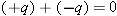


 . The atom, which is now an induced dipole, makes an electric field
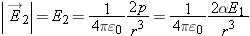
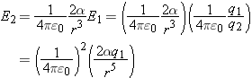
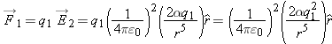
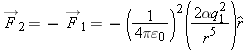


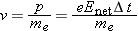


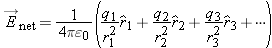
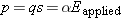
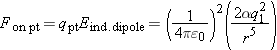
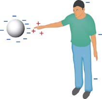
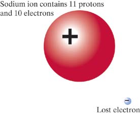
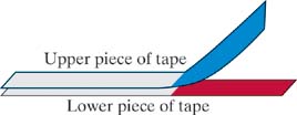
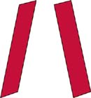

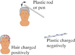

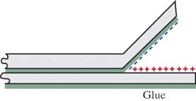
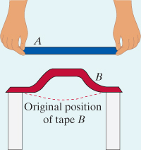
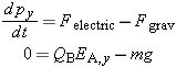
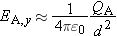
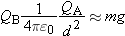
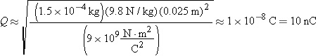

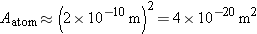
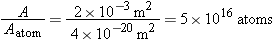
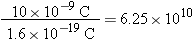
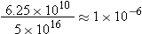
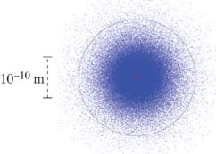
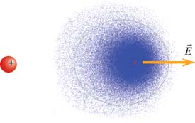

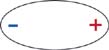

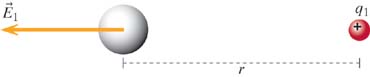
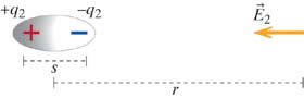
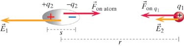
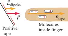
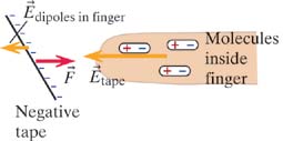

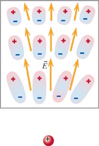
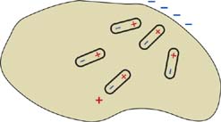
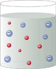
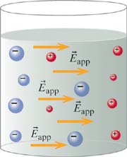
 ), the liquid polarizes. There is a slight excess ion concentration at the two sides of the beaker. The electric field due
to the redistributed ions is not shown.
), the liquid polarizes. There is a slight excess ion concentration at the two sides of the beaker. The electric field due
to the redistributed ions is not shown. .
.
 is the magnitude of the net electric field at the location of the mobile charge.