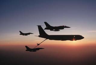
 | | Midair refueling offers an interesting example of relative velocity. To refuel, the lower plane matches its velocity to that of the tanker (the larger aircraft) and couples to the tanker’s delivery tube. During refueling, the relative velocity of the two planes is zero. (© George Hall/Corbis Images) |
|
To someone hitchhiking along a highway, two cars speeding by in adjacent lanes seem like a blur. But if the cars have the same velocity, each driver sees the other remaining in place, one lane away. The hitchhiker observes a velocity of perhaps 30 m/s, but each driver observes the other’s velocity to be zero. Clearly, the velocity of an object is relative to the observer who is making the measurement.
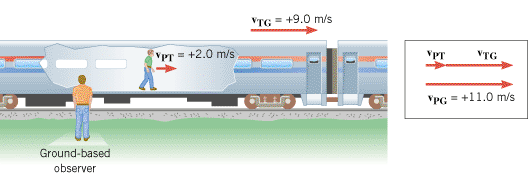
Figure 3.16 illustrates the concept of relative velocity by showing a passenger walking toward the front of a moving train. The people sitting on the train see the passenger walking with a velocity of +2.0 m/s, where the plus sign denotes a direction to the right. Suppose the train is moving with a velocity of +9.0 m/s relative to an observer standing on the ground. Then the ground-based observer would see the passenger moving with a velocity of +11 m/s, due in part to the walking motion and in part to the train’s motion. As an aid in describing relative velocity, let us define the following symbols:
In terms of these symbols, the situation in Figure 3.16 can be summarized as follows:
 | (3.7) |  |
or
According to Equation 3.7, vPG is the vector sum of vPT and vTG, and this sum is shown in the drawing. Had the passenger been walking toward the rear of the train, rather than the front, the velocity relative to the ground-based observer would have been  .
.
 | Figure 3.16
The velocity of the passenger relative to the ground-based observer is vPG. It is the vector sum of the velocity vPT of the passenger relative to the train and the velocity vTG of the train relative to the ground:vPG = = vPT+vTG. vPT+vTG. |
|
Each velocity symbol in Equation 3.7 contains a two-letter subscript. The first letter in the subscript refers to the body that is moving, while the second letter indicates the object relative to which the velocity is measured. For example, vTG and vPG are the velocities of the Train and Passenger measured relative to the Ground. Similarly, vPT is the velocity of the Passenger measured by an observer sitting on the Train.
The ordering of the subscript symbols in Equation 3.7 follows a definite pattern. The first subscript (P) on the left side of the equation is also the first subscript on the right side of the equation. Likewise, the last subscript (G) on the left side is also the last subscript on the right side. The third subscript (T) appears only on the right side of the equation as the two “inner” subscripts. The colored boxes below emphasize the pattern of the symbols in the subscripts:
In other situations, the subscripts will not necessarily be P, G, and T, but will be compatible with the names of the objects involved in the motion.
| Check Your Understanding 4 |
 | | Figure 3.17
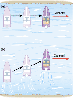
(a) A boat with its engine turned off is carried along by the current. (b) With the engine turned on, the boat moves across the river in a diagonal fashion. |
|
Equation 3.7 has been presented in connection with one-dimensional motion, but the result is also valid for two-dimensional motion. Figure 3.17 depicts a common situation that deals with relative velocity in two dimensions. Part a of the drawing shows a boat being carried downstream by a river; the engine of the boat is turned off. In part b, the engine has been turned on, and now the boat moves across the river in a diagonal fashion because of the combined motion produced by the current and the engine. The list below gives the velocities for this type of motion and the objects relative to which they are measured:
 |  |
The velocity vBW of the boat relative to the water is the velocity measured by an observer who, for instance, is floating on an inner tube and drifting downstream with the current. When the engine is turned off, the boat also drifts downstream with the current, and vBW is zero. When the engine is turned on, however, the boat can move relative to the water, and vBW is no longer zero. The velocity vWS of the water relative to the shore is the velocity of the current measured by an observer on the shore. The velocity vBS of the boat relative to the shore is due to the combined motion of the boat relative to the water and the motion of the water relative to the shore. In symbols,
The ordering of the subscripts in this equation is identical to that in Equation 3.7, although the letters have been changed to reflect a different physical situation. Example 10 illustrates the concept of relative velocity in two dimensions.
| Example 10 Crossing a River |
Occasionally, situations arise when two vehicles are in relative motion, and it is useful to know the relative velocity of one with respect to the other. Example 11 considers this type of relative motion.
 Concept Simulation 3.3 Concept Simulation 3.3 |
 |
This simulation illustrates the concept of relative velocity by considering a boat traveling across a flowing river. You can change the speed and direction of the boat relative to the water, as well as the velocity of the water. The simulation then shows the velocity of the boat as viewed by a person standing on the shore. |
|
 |
| Example 11 Approaching an Intersection |
 |
|
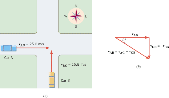
Figure 3.19a shows two cars approaching an intersection along perpendicular roads. The cars have the following velocities:
Find the magnitude and direction of vAB, where
 | | Figure 3.19
Two cars are approaching an intersection along perpendicular roads. |
|
Reasoning
To find vAB, we use an equation whose subscripts follow the order outlined earlier. Thus,
In this equation, the term vGB is the velocity of the ground relative to a passenger in car B, rather than vBG, which is given as 15.8 m/s, northward. In other words, the subscripts are reversed. However, vGB is related to vBG according to
This relationship reflects the fact that a passenger in car B, moving northward relative to the ground, looks out the car window and sees the ground moving southward, in the opposite direction. Therefore, the equation vAB = = vAG+vGB may be used to find vAB, provided we recognize vGB as a vector that points opposite to the given velocity vBG. With this in mind, Figure 3.19 illustrates how vAG and vGB are added vectorially to give vAB. vAG+vGB may be used to find vAB, provided we recognize vGB as a vector that points opposite to the given velocity vBG. With this in mind, Figure 3.19 illustrates how vAG and vGB are added vectorially to give vAB.
Problem solving insight
In general, the velocity of object R relative to object S is always the negative of the velocity of object S relative to R: vRS = = –vSR –vSR |
|
Solution
From the vector triangle in Figure 3.19b, the magnitude and direction of vAB can be calculated as
and
|
 |
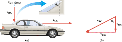
While driving a car, have you ever noticed that the rear window sometimes remains dry, even though rain is falling? This phenomenon is a consequence of relative velocity, as Figure 3.20 helps to explain. Part a shows a car traveling horizontally with a velocity of vCG and a raindrop falling vertically with a velocity of vRG. Both velocities are measured relative to the ground. To determine whether the raindrop hits the window, however, we need to consider the velocity of the raindrop relative to the car, not the ground. This velocity is vRC, and we know that
 |  |
Here, we have used the fact that  . Part b of the drawing shows the tail-to-head arrangement corresponding to this vector addition and indicates that the direction of vRC is given by the angle q R. In comparison, the rear window is inclined at an angle q W with respect to the vertical (see the blowup in part a). When q R is greater than q W, the raindrop will miss the window. However, q R is determined by the speed vRG of the raindrop and the speed vCG of the car, according to
  . At higher car speeds, the angle q R becomes too large for the drop to hit the window. At a high enough speed, then, the car simply drives out from under each falling drop
 | Figure 3.20
(a) With respect to the ground, a car is traveling at a velocity of vCG and a raindrop is falling at a velocity of vRG. The rear window of the car is inclined at an angle q W with respect to the vertical. (b) This tail-to-head arrangement of vectors corresponds to the equation vRC = = vRG–vCG. vRG–vCG. |
|
 |
|
Test your understanding of the key ideas in Section 3.4:
· Relative Velocity · Vector Addition of Relative Velocities
|
|
 |
 |
| Copyright © 2000-2003 by John Wiley & Sons, Inc. or related companies. All rights reserved. |


 .
.


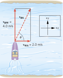
 . The time for the boat to cross the river is equal to the width of the river divided by the magnitude of this


 . Part
  . At higher car speeds, the angle
