Section 18.6 discusses how a point charge creates an electric field in the space around the charge. There are also many situations in which an electric field is produced by charges that are spread out over a region, rather than by a single point charge. Such an extended collection of charges is called a charge distribution. For example, the electric field within the parallel plate capacitor in Figure 18.22 is produced by positive charges spread uniformly over one plate and an equal number of negative charges spread over the other plate. As we will see, Gauss’ law describes the relationship between a charge distribution and the electric field it produces.
 CONCEPTS AT A GLANCE In presenting Gauss’ law, it will be necessary to introduce a new idea called electric flux, and the Concepts-at-a-Glance chart in Figure 18.32 outlines the approach we will follow. This figure is an extended version of the concept chart in Figure 18.16 because the idea of flux involves both the electric field and the surface through which it passes. By bringing together the electric field and the surface through which it passes, we will be able to define electric flux and then present Gauss’ law.
|
| Figure 18.32
CONCEPTS AT A GLANCE The electric field and the surface through which it passes are brought together to define the concept of electric flux. It is in terms of electric flux that Gauss’ law is formulated. When the electric field is produced by a distribution of charges, such as that on the silvery metal sphere in the photograph, Gauss’ law relates the electric flux to the charge. (© Charles D. Winters/Photo Researchers) |
|
We begin by developing a version of Gauss’ law that applies only to a point charge, which we assume to be positive. The electric field lines for a positive point charge radiate outward in all directions from the charge, as Figure 18.23b indicates. The magnitude E of the electric field at a distance r from the charge is E =
= kq/r2, according to Equation 18.3, in which we have replaced the symbol |q| with the symbol q since we are assuming that the charge is positive. As mentioned in Section 18.5, the constant k can be expressed as k
 =
= 1/(4pe0), where e0 is the permittivity of free space. With this substitution, the magnitude of the electric field becomes E
 =
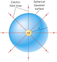
= q/(4pe0r2). We now place this point charge at the center of an imaginary spherical surface of radius r, as Figure 18.33 shows. Such a hypothetical closed surface is called a Gaussian surface, although in general it need not be spherical. The surface area A of a sphere is A
 =
= 4pr2, and the magnitude of the electric field can be written in terms of this area as E
 =
= q/(Ae0), or
 | (18.5) |  |
The left side of Equation 18.5 is the product of the magnitude E of the electric field at any point on the Gaussian surface and the area A of the surface. In Gauss’ law this product is especially important and is called the electric flux, FE: FE =
= EA. (It will be necessary to modify this definition of flux when we consider the general case of a Gaussian surface with an arbitrary shape.)
 | | Figure 18.33
A positive point charge is located at the center of an imaginary spherical surface of radius r. Such a surface is one example of a Gaussian surface. Here the electric field is perpendicular to the surface and has the same magnitude everywhere on it. |
|
Equation 18.5 is the result we have been seeking, for it is the form of Gauss’ law that applies to a point charge. This result indicates that, aside from the constant e0, the electric flux FE depends only on the charge q within the Gaussian surface and is independent of the radius r of the surface. We will now see how to generalize Equation 18.5 to account for situations where the electric field is produced by a distribution of charges and the Gaussian surface has an arbitrary shape.
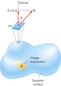
Figure 18.34 shows a charge distribution whose net charge is labeled Q. The charge distribution is surrounded by a Gaussian surface—that is, an imaginary closed surface. The surface can have any arbitrary shape (it need not be spherical), but it must be closed (an open surface would be like that of half an eggshell). The direction of the electric field is not necessarily perpendicular to the Gaussian surface. Furthermore, the magnitude of the electric field need not be constant on the surface, but can vary from point to point.
 | Figure 18.34
The charge distribution Q is surrounded by an arbitrarily shaped Gaussian surface. The electric flux F through any tiny segment of the surface is the product of E cos
f
and the area D
A of the segment: F
 =
=
 (E cos
f
) D
A. The angle
f
is the angle between the electric field and the normal to the surface. (E cos
f
) D
A. The angle
f
is the angle between the electric field and the normal to the surface. |
|
To determine the electric flux through such a surface, we divide the surface into many tiny sections with areas DA1, DA2, and so on. Each section is so small that it is essentially flat and the electric field E is a constant (both in magnitude and direction) over it. For reference, a dashed line called the “normal” is drawn perpendicular to each section on the outside of the surface. To determine the electric flux for each of the sections, we use only the component of E that is perpendicular to the surface—that is, the component of the electric field that passes through the surface. From the drawing it can be seen that this component has a magnitude of E cos f, where f is the angle between the electric field and the normal. The electric flux through any one section is then (E cos f)DA. The electric flux FE that passes through the entire Gaussian surface is the sum of all of these individual fluxes: FE =
= (E1 cos f1)DA1
 +
+ (E2 cos f2)DA2
 +
+ ···, or
 | (18.6) |  |
where, as usual, the symbol S means “the sum of.” Gauss’ law relates the electric flux FE to the net charge Q enclosed by the arbitrarily shaped Gaussian surface.
| GAUSS’ LAW |
|
The electric flux FE through a Gaussian surface is equal to the net charge Q enclosed by the surface divided by e0, the permittivity of free space:
 | (18.7) |  |
SI Unit of Electric Flux: N·m2/C
|
Gauss’ law is often used to find the magnitude of the electric field produced by a distribution of charges. The law is most useful when the distribution is uniform and symmetrical. In the next two examples we will see how to apply Gauss’ law in such situations.
 Concept Simulation 18.3 Concept Simulation 18.3 |
 |
This simulation, in effect, is an extension of Example 14. In addition to the spherical shell treated in that example, the simulation includes the options of adding a sphere within the shell and a point charge at the center of the sphere. The magnitudes and algebraic signs of the charges on the three objects are under your control. Therefore, you can explore the effect that these charges have on the electric field lines, make predictions based on Gauss’ law, and see whether your predictions are consistent with the pattern of the field lines. Related Homework: Problem 52 |
|
 |
| Example 14 The Electric Field of a Charged Thin Spherical Shell |
 |
|
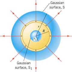
Figure 18.35 shows a thin spherical shell of radius R. A positive charge q is spread uniformly over the shell. Find the magnitude of the electric field at any point (a) outside the shell and (b) inside the shell.
 | | Figure 18.35
A uniform distribution of positive charge resides on a thin spherical shell of radius R. The spherical Gaussian surfaces S and S1 are used in Example 14 to evaluate the electric flux outside and inside the shell, respectively. |
|
Reasoning
Because the charge is distributed uniformly over the spherical shell, the electric field is symmetrical. This means that the electric field is directed radially outward in all directions, and its magnitude is the same at all points that are equidistant from the shell. All such points lie on a sphere, so the symmetry is called spherical symmetry. With this symmetry in mind, we will use a spherical Gaussian surface to evaluate the electric flux FE. We will then use Gauss’ law to determine the magnitude of the electric field.
Solution
| (a) |
To find the magnitude of the electric field outside the charged shell, we evaluate the electric flux FE = = S(E cos f)DA by using a spherical Gaussian surface of radius r (r > R) that is concentric with the shell. See the surface labeled S in Figure 18.35. Since the electric field E is everywhere perpendicular to the Gaussian surface, f S(E cos f)DA by using a spherical Gaussian surface of radius r (r > R) that is concentric with the shell. See the surface labeled S in Figure 18.35. Since the electric field E is everywhere perpendicular to the Gaussian surface, f = = 0° and cos f 0° and cos f = = 1. In addition, E has the same value at all points on the surface, since they are equidistant from the charged shell. Being constant over the surface, E can be factored outside the summation, with the result that
The term SDA is just the sum of the tiny areas that make up the Gaussian surface. Since the area of a spherical surface is 4pr2, we have SDA 1. In addition, E has the same value at all points on the surface, since they are equidistant from the charged shell. Being constant over the surface, E can be factored outside the summation, with the result that
The term SDA is just the sum of the tiny areas that make up the Gaussian surface. Since the area of a spherical surface is 4pr2, we have SDA = = 4pr2. Setting the electric flux equal to Q/e0, as specified by Gauss’ law, yields E(4pr2) 4pr2. Setting the electric flux equal to Q/e0, as specified by Gauss’ law, yields E(4pr2) = = Q/e0. Since the only charge within the Gaussian surface is the charge q on the shell, it follows that the net charge within the Gaussian surface is Q Q/e0. Since the only charge within the Gaussian surface is the charge q on the shell, it follows that the net charge within the Gaussian surface is Q = = q. Thus, we can solve for E and find that
This is a surprising result, for it is the same as that for a point charge (see Equation 18.3 with |q| q. Thus, we can solve for E and find that
This is a surprising result, for it is the same as that for a point charge (see Equation 18.3 with |q| = = q). Thus, the electric field outside a uniformly charged spherical shell is the same as if all the charge q were concentrated as a point charge at the center of the shell. q). Thus, the electric field outside a uniformly charged spherical shell is the same as if all the charge q were concentrated as a point charge at the center of the shell.
| | (b) |
To find the magnitude of the electric field inside the charged shell, we select a spherical Gaussian surface that lies inside the shell and is concentric with it. See the surface labeled S1 in Figure 18.35. Inside the charged shell, the electric field (if it exists) must also have spherical symmetry. Therefore, using reasoning like that in part (a), the electric flux through the Gaussian surface is FE = = S(E cos f)DA S(E cos f)DA = = E(4pr12). In accord with Gauss’ law, the electric flux must be equal to Q/e0, where Q is the net charge inside the Gaussian surface. But now Q E(4pr12). In accord with Gauss’ law, the electric flux must be equal to Q/e0, where Q is the net charge inside the Gaussian surface. But now Q = = 0 C, since all the charge lies on the shell that is outside the surface S1. Consequently, we have E(4pr12) 0 C, since all the charge lies on the shell that is outside the surface S1. Consequently, we have E(4pr12) = = Q/e0 Q/e0 = = 0, or
Gauss’ law allows us to deduce that there is no electric field inside a uniform spherical shell of charge. An electric field exists only on the outside. 0, or
Gauss’ law allows us to deduce that there is no electric field inside a uniform spherical shell of charge. An electric field exists only on the outside.
|
|
 |
| Example 15 The Electric Field Inside a Parallel Plate Capacitor |
 |
|
According to Equation 18.4, the electric field inside a parallel plate capacitor, and away from the edges, is constant and has a magnitude of E = = s/e0, where s is the charge density (the charge per unit area) on a plate. Use Gauss’ law to prove this result. s/e0, where s is the charge density (the charge per unit area) on a plate. Use Gauss’ law to prove this result.
Reasoning
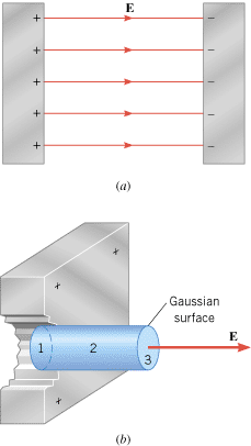
Figure 18.36a shows the electric field inside a parallel plate capacitor. Because the positive and negative charges are distributed uniformly over the surfaces of the plates, symmetry requires that the electric field be perpendicular to the plates. We will take advantage of this symmetry by choosing our Gaussian surface to be a small cylinder whose axis is perpendicular to the plates (see part b of the figure). With this choice, we will be able to evaluate the electric flux and then, with the aid of Gauss’ law, determine E.
 | | Figure 18.36
(a) A side view of a parallel plate capacitor, showing some of the electric field lines. (b) The Gaussian surface is a cylinder oriented so its axis is perpendicular to the positive plate and its left end is inside the plate. |
|
Solution
Figure 18.36b shows that we have placed our Gaussian cylinder so that its left end is inside the positive metal plate, and the right end is in the space between the plates. To determine the electric flux through this Gaussian surface, we evaluate the flux through each of the three parts—labeled 1, 2, and 3 in the drawing—that make up the total surface of the cylinder and then add up the fluxes.
Surface 1—the flat left end of the cylinder—is embedded inside the positive metal plate. As discussed in Section 18.8, the electric field is zero everywhere inside a conductor that is in equilibrium under electrostatic conditions. Since E = = 0 N/C, the electric flux through this surface is also zero: 0 N/C, the electric flux through this surface is also zero:
Surface 2—the curved wall of the cylinder—is everywhere parallel to the electric field between the plates, so that cos f = = cos 90° cos 90° = = 0. Therefore, the electric flux through this surface is also zero:
Surface 3—the flat right end of the cylinder—is perpendicular to the electric field between the plates, so cos f 0. Therefore, the electric flux through this surface is also zero:
Surface 3—the flat right end of the cylinder—is perpendicular to the electric field between the plates, so cos f = = cos 0° cos 0° = = 1. The electric field is constant over this surface, so E can be taken outside the summation in Equation 18.6. Noting that SDA 1. The electric field is constant over this surface, so E can be taken outside the summation in Equation 18.6. Noting that SDA = = A is the area of surface 3, we find that the electric flux through this surface is
The electric flux through the entire Gaussian cylinder is the sum of the three fluxes determined above:
According to Gauss’ law, we set the electric flux equal to Q/e0, where Q is the net charge inside the Gaussian cylinder: EA A is the area of surface 3, we find that the electric flux through this surface is
The electric flux through the entire Gaussian cylinder is the sum of the three fluxes determined above:
According to Gauss’ law, we set the electric flux equal to Q/e0, where Q is the net charge inside the Gaussian cylinder: EA = = Q/e0. But Q/A is the charge per unit area, s, on the plate. Therefore, we arrive at the value of the electric field inside a parallel plate capacitor: Q/e0. But Q/A is the charge per unit area, s, on the plate. Therefore, we arrive at the value of the electric field inside a parallel plate capacitor:  . Notice that the distance of the right end of the Gaussian cylinder from the positive plate does not appear in this result, indicating that the electric field has the same value everywhere between the plates. . Notice that the distance of the right end of the Gaussian cylinder from the positive plate does not appear in this result, indicating that the electric field has the same value everywhere between the plates.
|
 |
| Check Your Understanding 4 |
 |
|
The drawing shows an arrangement of three charges. In parts (a) and (b) different Gaussian surfaces are shown. Through which surface, if either, does the greater electric flux pass?
Background:
Electric flux is defined in terms of the electric field and the surface area through which the field passes. Gauss’ law is formulated in terms of electric flux and relates the flux to the net electric charge.
For similar questions (including calculational counterparts), consult Self-Assessment Test 18.2, which is described next.
|
|
 |
| Self-Assessment Test 18.2 |
 |
|
Test your understanding of the material in Sections 18.6, 18.7, 18.8 and 18.9:
· The Electric Field · Electric Field Lines · Gauss’ Law
|
|
 |
 |
| Copyright © 2000-2003 by John Wiley & Sons, Inc. or related companies. All rights reserved. |
![]() CONCEPTS AT A GLANCE In presenting Gauss’ law, it will be necessary to introduce a new idea called electric flux, and the Concepts-at-a-Glance chart in Figure 18.32 outlines the approach we will follow. This figure is an extended version of the concept chart in Figure 18.16 because the idea of flux involves both the electric field and the surface through which it passes. By bringing together the electric field and the surface through which it passes, we will be able to define electric flux and then present Gauss’ law.
CONCEPTS AT A GLANCE In presenting Gauss’ law, it will be necessary to introduce a new idea called electric flux, and the Concepts-at-a-Glance chart in Figure 18.32 outlines the approach we will follow. This figure is an extended version of the concept chart in Figure 18.16 because the idea of flux involves both the electric field and the surface through which it passes. By bringing together the electric field and the surface through which it passes, we will be able to define electric flux and then present Gauss’ law.![]() =
=![]() kq/r2, according to Equation 18.3, in which we have replaced the symbol |q| with the symbol q since we are assuming that the charge is positive. As mentioned in Section 18.5, the constant k can be expressed as k
kq/r2, according to Equation 18.3, in which we have replaced the symbol |q| with the symbol q since we are assuming that the charge is positive. As mentioned in Section 18.5, the constant k can be expressed as k![]() =
=![]() 1/(4pe0), where e0 is the permittivity of free space. With this substitution, the magnitude of the electric field becomes E
1/(4pe0), where e0 is the permittivity of free space. With this substitution, the magnitude of the electric field becomes E![]() =
=![]() q/(4pe0r2). We now place this point charge at the center of an imaginary spherical surface of radius r, as Figure 18.33 shows. Such a hypothetical closed surface is called a Gaussian surface, although in general it need not be spherical. The surface area A of a sphere is A
q/(4pe0r2). We now place this point charge at the center of an imaginary spherical surface of radius r, as Figure 18.33 shows. Such a hypothetical closed surface is called a Gaussian surface, although in general it need not be spherical. The surface area A of a sphere is A![]() =
=![]() 4pr2, and the magnitude of the electric field can be written in terms of this area as E
4pr2, and the magnitude of the electric field can be written in terms of this area as E![]() =
=![]() q/(Ae0), or
q/(Ae0), or
![]() =
=![]() EA. (It will be necessary to modify this definition of flux when we consider the general case of a Gaussian surface with an arbitrary shape.)
EA. (It will be necessary to modify this definition of flux when we consider the general case of a Gaussian surface with an arbitrary shape.)

![]() =
=![]() (E1 cos f1)DA1
(E1 cos f1)DA1![]() +
+![]() (E2 cos f2)DA2
(E2 cos f2)DA2![]() +
+![]() ···, or
···, or
 Concept Simulation 18.3
 . Notice that the distance of the right end of the Gaussian cylinder from the positive plate does not appear in this result, indicating that the electric field has the same value everywhere between the plates.